Sketch architectural design. Development of an architectural concept: draft design. The main sections of the draft design
Inclusion in building production always starts with the development of the project. In this article, we will consider what project documentation is, what is its composition and share personal experience for the development of projects of varying complexity. Despite the fact that the term “project work” itself is all-encompassing, almost immediately giving a direction to the English “project” - more appropriate in meaning, as the implementation of ideas, the most clear explanation will be required, taking into account the creative approach to project activities.
Design stages:
First stage Pre-project stage of works
1.Performance of pre-project calculations (determination of the structural scheme of the building, materials and estimated estimates for construction), we will help you meet a certain amount Money, the feasibility of construction will be assessed.
2. Formation of a package of legal documents for obtaining initial permits for design and construction, legal analysis of existing documents, consultations.

Second stage Implementation draft design(concepts) and architectural and planning solutions
1. Development of a booklet of a draft proposal (concept) - development of an architectural volume-spatial solution and technical and economic indicators, visualization. A draft design is a material that allows you to evaluate the project and form precise requirements for further design. The draft design performs the functions of the primary document necessary for passing the regulatory commission and obtaining the initial permits.
The sketch is developed in order to establish functional, constructive and style solutions for the project, which give a general idea of the future object and the process of interaction of individual parts of the project with each other. In the future, the draft design becomes the basis for writing the Terms of Reference for all subsequent design stages.
- Based on the draft design, constructive and architectural solutions, layout, number of storeys, material, Technical equipment; all this gives a clear idea of the organization of the plan, the volumetric structure and the appearance of the future structure.

2*. Additionally, for the concept, the calculation of the estimated cost of the object and the stages of investing funds.
The outline design includes the following sections:
- Scheme of the master plan М 1:500
- Transport scheme
- Plans
- cuts
- facades
- Visualization and photomontage
- Calculations (for the concept)

The third stage Implementation of the working project
1. Development of all necessary sections of the working draft in accordance with the requirements and standards in the field of construction. Before proceeding with the construction of the facility, it is necessary to clearly understand the front of the upcoming work. It is important to work out all the details at the design stage. Therefore, much attention is paid to project documentation, in which all technical aspects are worked out in detail. The composition of the project documentation is sufficient for the approval and implementation of the construction object. Such documentation allows you to determine the costs of construction and installation work with maximum accuracy and is used throughout the entire construction process.

2*.Optional. Performing Customer Service Functions: Receiving specifications, coordination of project documentation in established instances.
The working draft includes the following sections:
- Master plan and transport
- Architectural and construction part
- Structural part
- Engineering
- Technological part
- Security section environment
- Construction organization project
- Estimated documentation

Design of warehouse and industrial buildings Work in one stage - Implementation of a working project
1. Performing pre-project calculations (determining the structural scheme of the building, materials and estimated estimates for construction), we will help you meet a certain amount of money.
2. Development of all necessary sections of the working draft in accordance with the requirements and standards in the field of construction.
3*.Optional. Performing the functions of the Customer's service: obtaining technical specifications, coordinating project documentation in established authorities.
The working draft includes the following sections:
- Master plan and transport
- Structural part
- Engineering
- Technological part
- Estimated documentation
Do you need a project? To save your time, we suggest you contact our specialists by phone 209-09-40. You can also use the online feedback on this site or write us an e-mail!
They rarely think about how important it is to correctly draw up a draft design of a planned object. But any construction should begin from this stage. Moreover, by the time the first brick or log is brought to the construction site, the sketch must already be agreed, developed and approved.
After all, without it, the customer (that is, you) will not be able to form a correct idea of how the constructed building will look like. But this should be represented not only by you, but also by the builders who will carry out the entire workflow. Therefore, it is worth taking this issue seriously, understanding it to the smallest detail.
To begin with, a draft design of a house is a set primary documents, which is necessary to
And also correctly draw up all the documentation used directly in this case. Having a sketch of the house in hand, you can easily formulate your requirements when communicating with the designers who will develop.
How it is compiled
You are contacting a company that provides services for . First of all, after the conclusion of the contract, you talk with the architect.

An experienced specialist in a simple and accessible form will ask you about exactly how the house that you would like to receive should look like. Perhaps you will bring photographs of buildings that would suit you to the fullest. But it is possible that you will have certain wishes: change the shape and location of the windows, use a tiled roof instead of a slate roof, and a number of other minor changes.
All these wishes will be taken into account by the architect, who, after talking with you, will start work.
For an experienced specialist, the development of a draft design will take no more than a few days.
After that, you will be presented with a set of diagrams and color illustrations, allowing you to fully appreciate the external and internal appearance of the future home. Yes, it might surprise some people why you need to design a project from scratch if you already know what your house will look like.
 Sample House Plan
 After all, it will take a lot of money and time. And yet, drawing up a sketch is not at all a trick of specialists who want to take your time and extract extra money from you. After all, any changes in the appearance of the building, even the most insignificant, can seriously affect its entire structure.
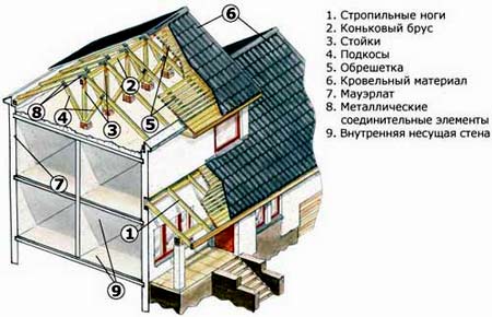
The simplest example: you decide to enlarge the window? This means that the load on the entire window opening will increase significantly. And it will definitely need to be strengthened so that he can withstand it without harm to himself. Do you want to use ceramic tiles instead of metal tiles? This means that the rafters will have to be strengthened so that they can withstand a significantly increased load.
Of course, it is simply impossible to carry out all these calculations by eye, without drawing up a special sketch or project. In addition, the finished sketch allows you to quite accurately determine the complexity of the work and the amount of required materials. And, therefore, you will be called the price of the house.
Read also
Projects and construction of houses made of stone and brick
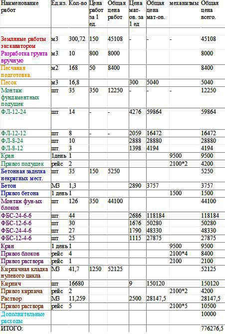 An example of a cost estimate for materials
 Moreover, specialists will be able to calculate for you separately the cost of building and finishing materials, as well as the cost of the work carried out. And this is very important. Perhaps not a single reasonable person will agree to start building a country cottage, not knowing exactly how much it will cost him.
The sketch necessarily contains a number of illustrations by which you can evaluate your future home from the inside and outside.
The use of modern architectural programs allows you to make the sketch as clear as possible.
It remains for you to decide whether all your requirements have been taken into account during the construction, or if you would like to make additional changes, having achieved maximum compliance with the plans that you are hatching.
What you need to conclude a contract for drawing up a sketch
Designing a sketch is a very difficult and responsible job. Of course, it is carried out only after the conclusion of an agreement with the company. And for this you will need to collect the following documents:
- Terms of reference for design. Here it is necessary to writing present your requirements, which the future object must meet;
- Town-planning plan of the land plot;
- Geodetic survey of a land plot (scale 1:500);
- Certification that the available footage is usable.
When these documents are collected, you can safely go to sign a contract for the provision of services. Immediately after that, you will be directed to the architect-designer to coordinate all the work. Having received all the necessary information from you (in addition to the terms of reference), he proceeds to develop a sketch.
 House sketch example
 It is worth saying that the creation of a sketch is a very difficult and responsible stage. From the outside it may seem that everything is quite easy and simple here: every person can do what he would like to live in. However, drawing up and drawing a sketch with your own hands very often leads to sad consequences. Still, the finished illustrations that are shown to you along with the sketch are just the tip of the iceberg. And the gigantic amount of work done remains in the drawings, which will say little to a person who has nothing to do with construction.
After all, in order to draw up a sketch, a specialist conducts a series of calculations, which are later used to develop a project for which construction will be carried out. And a non-professional is unlikely to be able to do all the work with the same quality, guaranteeing the integrity and durability of the structure, as a specialist who has got his hand on this for many years of work.
 house design example
 To more clearly explain how many factors have to be taken into account when developing a draft design of a building, it is worth listing the main ones.
Location on the site
When placing housing on a land plot, it is necessary to comply with a number of requirements for sanitary and fire safety, as well as building standards. The distance from the house to the border of the neighboring plot must be at least the established minimum. It is also necessary to correctly orient the house relative to the cardinal points. Technical rooms are best placed on the north side, while residential rooms should be placed on the south.
Of course, the house should gracefully fit into the surrounding landscape, and not stand out from it.
When drawing up the general plan of the site, an experienced architect will successfully place on it not only the house itself, but also all the buildings that the owner of the site considers necessary. It may be a number of other buildings.
GOST 2.119-2013
INTERSTATE STANDARD
one system design documentation
PRELIMINARY DESIGN
Unified system for design documentation Preliminary design
For the text of Comparison of GOST 2.119-2013 with GOST 2.119-73, see the link.
- Database manufacturer's note.
____________________________________________________________________
ISS 01.110
OKSTU 0002
Introduction date 2015-07-01
Foreword
Foreword
The goals, basic principles and basic procedure for carrying out work on interstate standardization are established in GOST 1.0-2015 "Interstate standardization system. Basic provisions" and GOST 1.2-2015 "Interstate standardization system. Interstate standards, rules and recommendations for interstate standardization. Rules for the development, adoption , updates and cancellations"
About the standard
1 DEVELOPED by the Federal State unitary enterprise"All-Russian Research Institute for Standardization and Certification in Mechanical Engineering" (VNIINMASH), Autonomous non-profit organization Research Center for CALS Technologies "Applied Logistics" (ANO R&D Center for CALS Technologies "Applied Logistics")
2 INTRODUCED by the Federal Agency for Technical Regulation and Metrology
3 ADOPTED by the Interstate Council for Standardization, Metrology and Certification (Minutes No. 44 of November 14, 2013, Appendix No. 24 add.)
Voted to accept:
Short name of the country according to MK (ISO 3166) 004-97 | Abbreviated name of the national standards body |
|
Azerbaijan | Azstandard |
|
Ministry of Economy of the Republic of Armenia |
||
Belarus | State Standard of the Republic of Belarus |
|
Kazakhstan | State Standard of the Republic of Kazakhstan |
|
Kyrgyzstan | Kyrgyzstandart |
|
Institute for Standardization of Moldova |
||
Rosstandart |
||
Tajikistan | Tajikstandart |
|
Uzbekistan | Uzstandard |
|
Ministry of Economic Development of Ukraine |
4 By order of the Federal Agency for Technical Regulation and Metrology of November 26, 2014 N 1794-st, the interstate standard GOST 2.119-2013 was put into effect as a national standard Russian Federation from July 01, 2015
5 INSTEAD OF GOST 2.119-73
6 REVISION as amended (IUS N 7 2015). December 2018
Information about changes to this standard is published in the annual information index "National Standards" (as of January 1 of the current year), and the text of changes and amendments - in the monthly information index "National Standards". In case of revision (replacement) or cancellation of this standard, a corresponding notice will be published in the monthly information index "National Standards". Relevant information, notification and texts are also placed in information system general use - on the official website of the Federal Agency for Technical Regulation and Metrology on the Internet (www.gost.ru)
1 area of use
This standard establishes requirements for the implementation of a draft design for products in all industries.
On the basis of this standard, it is allowed, if necessary, to develop standards that clarify the range of design documents being developed and the list of work performed at the preliminary design stage, taking into account the specifics of the designed products and the organization of work.
2 Normative references
This standard uses normative references to the following interstate standards:
GOST 2.002-72 Unified system for design documentation. Requirements for models, layouts and templates used in the design.
GOST 2.052-2015 Unified system for design documentation. Electronic product model. General provisions
GOST 2.053-2013 Unified system for design documentation. Electronic structure of the product. General provisions
GOST 2.102-2013 Unified system for design documentation. Types and completeness of design documents
GOST 2.103-2013 Unified system for design documentation. Development stages
GOST 2.106-96 Unified system for design documentation. Text Documents
GOST 2.118-2013 Unified system for design documentation. Technical Proposal
GOST 2.201-80 Unified system for design documentation. Designation of products and design documents
GOST 2.301-68 Unified system for design documentation. Formats
GOST 2.501-2013 Unified system for design documentation. Accounting and storage rules
GOST 2.503-2013 Unified system for design documentation. Rules for making changes
Note - When using this standard, it is advisable to check the validity of reference standards in the public information system - on the official website of the Federal Agency for Technical Regulation and Metrology on the Internet or according to the annual information index "National Standards", which was published as of January 1 of the current year, and on issues of the monthly information index "National Standards" for the current year. If the reference standard is replaced (modified), then when using this standard, you should be guided by the replacing (modified) standard. If the referenced standard is canceled without replacement, the provision in which the reference to it is given applies to the extent that this reference is not affected.
3 Terms, definitions and abbreviations
3.1 Terms and definitions
In this standard, the following terms are used with their respective definitions:
3.1.1
3.2 Abbreviations
The following abbreviations are used in this standard:
CD - design document (design documents, design documentation);
MF - an integral part of the product;
TK - terms of reference;
TP - technical proposal;
ESI - electronic model of a prefabricated unit *;
_____________
* The text of the document corresponds to the original. - Database manufacturer's note
EP - preliminary design;
ESI - electronic structure of the product.
EMSE is an electronic model of an assembly unit.
4 Fundamentals
4.1 EP is the design stage of development of design documentation (according to GOST 2.103) and it should be developed in accordance with the TOR in order to establish fundamental design solutions that give a general idea of the device, operating principles and overall dimensions of the product being developed, as well as data that determine its main parameters, when it is advisable to do this before the development of the TA or working design documentation.
At the stage of development of the ES, options for the product and (or) its SC should be considered. EP can be developed without considering various options at this stage.
4.2 Basic requirements for the development of CD EP in accordance with GOST 2.103, accounting and storage - in accordance with GOST 2.501; making changes - according to GOST 2.503.
4.3 When developing an electronic product, it is necessary to carry out the work necessary to ensure the requirements for the product and to establish fundamental solutions. Scroll necessary work is determined by the developer depending on the nature and purpose of the product and coordinates with the customer (representative office of the customer) if the product is being developed by order of the Ministry of Defense.
An approximate list of works is given in Appendix A.
Note - At the stage of development of the EP, the works given at the stage of development of the technical proposal should not be repeated if they cannot provide additional data. In this case, the results of previous work are reflected in explanatory note.
4.4 The set of design documentation for the ES should include design design documentation with the letters "E" in accordance with GOST 2.102, provided for by the TOR and / or the protocol for considering the technical proposal.
4.5 When performing design documentation in electronic form, projects of the ESI and the electronic model of the product (assembly unit, complex, kit) should be carried out in accordance with GOST 2.053 and GOST 2.052, respectively, with the level of detail characteristic of this development stage (ED).
CDs developed for the manufacture of material models in accordance with GOST 2.002, or electronic models developed in accordance with GOST 2.052, should not be included in the CD set of ES.
4.6 For verification, approval and approval, copies of the CD of the ES according to the ES statement, completed in the manner prescribed in GOST 2.106, should be submitted. It is allowed, in agreement with the customer (representative office of the customer), to submit the original CD ES.
4.7 The form of presentation of the CD of the ES (paper or electronic), if it is not specified in the ToR and / or the protocol for considering the technical proposal, must be determined by the developer in agreement with the customer (representative office of the customer), if the product is developed by order of the Ministry of Defense. In EP it is allowed to include in the design documentation in various forms representation.
4.8 The designation of the CD of the ES should be carried out in accordance with GOST 2.201 (Appendix 1).
5 Requirements for the execution of design documents
5.1 General requirements to the implementation of design documents of the draft design
5.2 Drawing general view(electronic model of assembly unit)
5.2.1 At the stage of development of the ES, the general view of the product can be made as a paper CD (general view drawing) or as an electronic CD (EMSE). In general, they should contain:
a) images of the product (views, sections, sections), the text part and inscriptions necessary for understanding the structural device of the product, its interaction constituent parts and the principle of operation of the product;
b) names, as well as designations (if any) of those SCs for which data must be specified ( specifications, quantity, instructions on the material, principle of operation, etc.) or a reference to which is necessary to explain the images of the general view drawing or EMSE, describe the principle of operation of the product, indicate the composition, etc .;
c) dimensions and other data applied to images (if necessary);
d) a diagram (electrical, hydraulic, etc.), if it is necessary, but it is not advisable to draw it up as a separate design documentation;
e) technical characteristics of the product, if necessary for the convenience of comparing options according to the general view drawing or EMSE.
5.2.2 Images should be made with the maximum simplifications provided by the standards unified system design documentation. MF products, including borrowed and purchased products, are depicted with simplifications (sometimes in the form of contour outlines), if this provides an understanding of the structural device of the product being developed, the interaction of its MF and the principle of operation of the product.
5.2.3 Separate MF images should be placed on one common sheet with images of the entire product or on separate (subsequent) sheets of the general view drawing.
When performing EMSE, it is recommended to place the models of individual midrange in separate files.
5.2.4 The names and designations of the MF in the general view drawing or EMCE should be indicated in one of the following ways:
a) on the shelves of leader lines;
b) in a table placed on the same sheet as the image of the product;
c) in a table made on separate sheets of A4 format in accordance with GOST 2.301 as subsequent sheets of a general view drawing. On the general view drawing or EMSE, it is recommended to indicate the names and designations of the midrange product using the methods a) and c). If there is a table on the shelves of leader lines, indicate the position numbers of the components included in the table.
The table generally consists of columns:
"Position", "Designation", "Name", "Quantity", "Additional instructions".
5.2.5 Names and designations of the SC in the table or ESI are recommended to be placed in the following order:
borrowed items;
purchased products;
newly developed products.
5.2.6 Elements of a general arrangement drawing or EMCE (item numbers, text technical requirements, inscriptions, etc.) are performed according to the rules established by the standards of the Unified System for Design Documentation.
5.3 Draft design sheet
All CDs should be entered in the ES statement in the manner established by GOST 2.106, regardless of which option the CD belongs to. It is allowed to indicate in the column "Note" the variant corresponding to this DD.
It is allowed to include in the DD in various forms of presentation (in paper or electronic), while it is recommended to indicate the form of presentation in the "Note" column.
5.4 Explanatory note
5.4.1 The explanatory note of the ES should be carried out in accordance with GOST 2.106, taking into account the following basic requirements for the content of the sections:
a) in the "Introduction" section, the name, number and date of approval of the TOR should be indicated. If the development of the ES is not provided for by the TOR, but by the protocol for considering the technical proposal, then an entry should be made according to the type: "Development of a preliminary design is provided for by the technical proposal ..." and indicate the number and date of the protocol for considering the technical proposal;
b) in the section "Purpose and scope of the product being developed", the relevant information from the TOR and / or technical proposal, as well as information specifying and supplementing the TOR and technical proposal, in particular:
- brief description scope and conditions of use of the product;
- general characteristics the facility for the application in which this product is intended (if necessary);
c) in the section "Technical characteristics" should be given:
- the main technical characteristics of the product (power, number of revolutions, productivity, consumption of electricity, fuel, efficiency and other parameters characterizing the product);
- information on compliance with or deviations from the requirements established by the TOR and the technical proposal, if it was developed, with justification for deviations;
- data comparing the main characteristics of the product with the characteristics of analogues (domestic and foreign) or a link should be given to a map of the technical level and quality;
d) in the section "Description and justification of the chosen design" should be given:
- description of the design, justification of the fundamental decisions made at this stage (constructive, circuit, etc.).
Illustrations should be provided where necessary. When performing an explanatory note in the form of an electronic CD, it is allowed to provide a link to electronic layouts (models) made in accordance with GOST 2.052;
- information about the purpose of material mock-ups (if they were made), electronic mock-ups (if they were developed), the test or analysis program and methodology (or a link to a separate CD - the test or analysis program and methodology), test or analysis results and mock-up conformity assessment data given requirements, including ergonomics and technical aesthetics;
- photos of material layouts (if necessary);
- designations of the main design documentation, according to which material models were made or electronic models were developed, the number and date of the reports (or protocols for testing, analysis, etc. (for reference);
- information about the manufacturability of the design of products;
- data from the verification of decisions made for patent purity and competitiveness;
- information about the use of inventions in this development, about submitted applications for new inventions;
- information on the compliance of the product with the requirements of safety and industrial sanitation;
- preliminary information about the packaging and transportation of the product (if necessary);
- technical requirements for purchased products and materials used in the product being developed, which must be developed by other organizations. Such technical requirements may be given in the appendix to the explanatory note;
- information on the compliance of the borrowed components used in the product, purchased products and materials with the developed product in terms of technical characteristics, operating modes, warranty periods, operating conditions;
- the main issues of manufacturing technology of products;
- information about the safety of the product and its impact on the environment;
Information on the disposal of the product;
e) in the section "Calculations confirming the operability and reliability of the design" should be given:
- indicative calculations confirming the performance of the product (kinematic, electrical, thermal, calculations of hydraulic systems, etc.);
- approximate calculations confirming the reliability of the product (calculations of reliability, durability, maintainability, shelf life, etc.). With a large amount of calculations, they can be drawn up in the form of independent design documentation, while in this section only the results of the calculations are given. For each type of calculation, software and information support automated systems(if they are used to perform calculations);
f) in the section "Description of the organization of work with the use of the product being developed", preliminary information on the organization of work with the product at the place of operation, including:
- description of techniques and methods of working with the product in the modes and conditions provided for by the TOR;
- description of the order and methods of storage, transportation, installation of the product and its commissioning at the place of operation, as well as maintenance during storage, transportation and installation;
- information on the qualifications and number of service personnel.
g) in the section "Expected technical and economic indicators", approximate calculations of economic indicators should be given;
i) in the "Level of standardization and unification" section, preliminary information on the use of standard, unified and borrowed assembly units and parts in the product being developed should be provided.
5.4.2 The appendix to the explanatory note should include:
a) a copy of the ToR;
b) if necessary, a list of works that should be carried out at the next stage of product development;
c) materials of artistic and design study, which are not design documentation;
d) list of used literature, etc.;
e) a list of documents used in the development of ES and received by the product developer from other organizations (author's certificates, patent research report, consumer certificates on the required production volume of the products being developed, etc.). At the same time, the documents should not be included in the annex to the explanatory note, but the explanatory note may contain the necessary information from these documents (for example, the subject of the invention, the required quantities of products for the quarter, for the year, for the five-year period), as well as the number and date of the document or cover letter
f) a list of software and information support for automated systems used in the development of ES.
Appendix A (recommended). List of works performed during the development of a draft design
In general, when developing a draft design, the following work should be carried out:
1 Execution of options possible solutions, establishing the features of the options (characteristics of the midrange options, etc.), their design study. The depth of such study should be sufficient to compare the options under consideration.
2 Preliminary decision on the issues of packaging, transportation and operation of the product.
3 Production and testing of material models and / or development and analysis of electronic models in order to verify the principles of operation of the product and / or its components.
4 Development and justification of technical solutions aimed at ensuring the reliability indicators established by the TOR and the technical proposal.
5 Evaluation of the product for manufacturability and the correct choice of means and methods of control (tests, analysis, measurements).
6 Evaluation of the product in terms of standardization and unification.
7 Evaluation of the product in relation to its compliance with the requirements of ergonomics, technical aesthetics. If necessary, to establish the ergonomic, aesthetic characteristics of the product and for the convenience of comparing various options for these characteristics, material mock-ups are made and (or) electronic mock-ups are developed.
8 Checking options for patent purity and competitiveness, filing applications for inventions.
9 Checking the compliance of options with the requirements of safety and industrial sanitation.
10 Comparative evaluation of the options under consideration, issues of metrological support of the product being developed (possibility of choosing methods and measuring instruments). The comparison is carried out in terms of product quality (purpose, reliability, manufacturability, standardization and unification, economic, aesthetic, ergonomic). At the same time, one should take into account the design and operational features of the developed and existing products, trends and prospects for the development of domestic and foreign technology in this area.
11 Selection of the optimal variant (options) of the product, rationale for the choice; making fundamental decisions; confirmation (or clarification) of the requirements for the product (technical characteristics, quality indicators, etc.) established by the TOR and the technical proposal, and the determination of technical and economic characteristics and indicators not established terms of reference and technical proposal.
12 Identification on the basis of the accepted fundamental decisions of new products and materials that should be developed by other organizations, drawing up technical requirements for these products and materials.
13 Drawing up a list of work to be carried out at a subsequent stage of development, in addition to or clarification of the work provided for by the TOR and the technical proposal.
14 Elaboration of the main issues of manufacturing technology (if necessary).
15 Preparation of proposals for the development of standards (revision and amendments to current standards) provided for by the TOR at this stage of development.
16 Elaboration of issues that ensure the possibility of using the design documentation in electronic form at subsequent stages of development.
17 Establishing the features of options, comparative evaluation of the options under consideration and the choice of the optimal variant (options) of the product, it is advisable to carry out on the basis of the functional electronic structure of the product, and the presentation and information of various options for the structure of the product in the form of a constructive electronic structure of the product in accordance with GOST 2.053.
UDC 002:744:006.354 | ||
Key words: design documentation, draft design, general view drawing, electronic product model, draft design sheet, draft design explanatory note |
||
Electronic text of the document
prepared by Kodeks JSC and verified against:
official publication
M.: Standartinform, 2018
INTERSTATE STANDARD
UNIFIED SYSTEM OF DESIGN DOCUMENTATION
MAIN PROVISIONS
PRELIMINARY DESIGN
GOST 2.119-73
IPK STANDARDS PUBLISHING HOUSE
1999
INTERSTATE STANDARD
|
Unified system of design documentation SKETCHPROJECT Unified system for design documentation. Preliminary design |
GOST |
By the Decree of the State Committee of Standards of the Council of Ministers of the USSR dated February 28, 1973 No. 501, the deadline for introducing
from 1974-01-01
This standard establishes requirements for the implementation of a draft design for products in all industries.
1. GENERAL PROVISIONS
1.1 . A preliminary design is developed if it is provided for by the terms of reference or the protocol for considering a technical proposal.
A draft design is developed in order to establish the fundamental (constructive, circuit, etc.) solutions of the product, giving a general idea of the principle of operation and (or) the device of the product, when it is advisable to do this before the development of a technical design or working documentation.
At the stage of developing a draft design, options for the product and (or) its components are considered. A draft design can be developed without considering various options at this stage.
1.2 . When developing a preliminary design, they perform the work necessary to ensure the requirements for the product and allow you to establish fundamental solutions. The list of necessary works is determined by the developer depending on the nature and purpose of the product and is agreed with the customer if the product is being developed by order of the Ministry of Defense.
An indicative list of works for national economic products is given in.
Note. At the preliminary design stage, the works given at the technical proposal stage are not repeated if they cannot provide additional data. In this case, the results of previous work are reflected in the explanatory note.
(Revised edition, Rev. No. 4).
1.3 . The set of draft design documents includes design documents, in accordance with GOST 2.102-68 provided for by the terms of reference and the protocol for consideration of the technical proposal. When documents are executed in electronic form, the electronic structure of the product and the electronic model of the product (assembly unit, complex) are performed with a degree of detail corresponding to the stage of the draft design.
Design documents developed for manufacturing material layouts according to GOST 2.002-72, are not included in the set of draft design documents.
(Changed edition, Change No. 5 )
1.4 . For consideration, approval and approval, copies of the draft design documents, completed according to GOST 2.106-96 . It is allowed, in agreement with the customer, to submit the original documents of the draft design.
1.5. The form of presentation of the preliminary design documents (paper or electronic), if it is not specified in the terms of reference and (or) the protocol for considering the technical proposal, is determined by the developer in agreement with the customer. Types of documents are set according to GOST 2.102-68 . It is allowed to include documents in various forms of representation in the set of documents of the draft design.
(Introduced additionally, Change No. 5 )
2. REQUIREMENTS FOR THE IMPLEMENTATION OF DOCUMENTS
2.1 .General requirements for the execution of documents
2.1.1 . Design documents containing various product options are performed according to GOST 2.118-73 in terms of posting information about various options, posting images of options, building tables containing data of various options, etc.
2.2 .General arrangement drawing
2.2.1 . At the draft design stage, a general view drawing or an equivalent electronic model of an assembly unit in the general case should contain:
a) images of the product (views, sections, sections), the text part and inscriptions necessary for understanding the structural device of the product, the interaction of its components and the principle of operation of the product;
b) names, as well as designations (if any) of those components of the product for which data must be specified (technical characteristics, quantity, instructions on the material, principle of operation, etc.) or link to which necessary to explain the images of the general view drawing, describe the principle of operation of the product, indicate the composition, etc.;
c) dimensions and other data applied to images (if necessary);
d) a scheme, if it is required, but it is not advisable to draw it up as a separate document;
e) technical characteristics of the product, if necessary for the convenience of comparing options according to the general view drawing.
(Changed edition, Change No. 5 )
2.2.2 . Images are performed with maximum simplifications provided for by the standards of the Unified Design Documentation System. The components of the product, including borrowed (previously developed) and purchased, are depicted with simplifications (sometimes in the form of contour outlines), if this provides an understanding of the structural device of the product being developed, the interaction of its components and the principle of operation of the product.
(Changed edition, Change No. 5 )
2.2.3 . Separate images of the component parts of the product are placed on one common sheet with images of the entire product or on separate (subsequent) sheets of the general view drawing.
When making a general view drawing in the form of an electronic model of an assembly unit, it is recommended that the models of individual components of the product be placed in separate files.
(Changed edition, Change No. 5 )
2.2.4 . The names and designations of the component parts of the product in the general view drawings are indicated in one of the following ways:
a) on the shelves of leader lines;
b) in a table placed on the same sheet as the image of the product;
c) in a table made on separate sheets of A4 format in accordance with GOST 2.301-68 as subsequent sheets of a general view drawing. In the general view drawing, made in the form of an electronic model of the assembly unit, it is recommended to indicate the names and designations of the component parts of the product using the methods a) and c).
If there is a table on the shelves of leader lines, indicate the position numbers of the components included in the table.
The table generally consists of columns: "Pos.", "Designation", "Name", "Col.", "Additional instructions".
When making a general view drawing in the form of an electronic model of an assembly unit, it is recommended to use the simultaneous display of the electronic structure of the product (instead of a table) and its electronic model, providing the possibility of highlighting (highlighting) the component of the electronic model when specifying the corresponding element of the electronic structure of the product.
(Changed edition, Change No. 5 )
2.2.5 . The names and designations of the product components in the table and (or) the electronic structure of the product are recommended to be placed in the following order:
borrowed items;
purchased products;
newly developed products.
(Changed edition, Change No. 5 )
2.2.6 . General arrangement drawing elements and (or) an equivalent electronic model of an assembly unit”; delete the words: “for working drawings(position numbers, text of technical requirements, inscriptions, etc.) are performed according to the rules established by the standards of the Unified Design Documentation System for working drawings.
(Changed edition, Change No. 5 )
2.3 .Draft design sheet
2.3.1 . All design documents included in the set of documents of the preliminary design are entered into the draft design sheet in the manner prescribed GOST 2.106-96 , regardless of which variant the document belongs to.
It is allowed in the column "Note" to indicate the corresponding this document option.
It is allowed to include in the set of documents of the draft design equivalent documents in various forms of presentation (in paper or electronic form), while in the column "Note" it is recommended to indicate the form of presentation of the document.
(Changed edition, Change No. 5 )
2.4 .Explanatory note
2.4.1 . The explanatory note of the draft design is carried out according to GOST 2.106-96 taking into account the following basic requirements for the content of sections:
a) in the section "Introduction" indicate the name, number and date of approval of the terms of reference. If the development of a preliminary design is provided not by the terms of reference, but by the protocol for considering the technical proposal, then an entry is made according to the type: “Development of the preliminary design is provided for by the technical proposal ...” and indicate the number and date of the protocol for considering the technical proposal;
b) in the section "Purpose and scope of the developed product" provide relevant information from the terms of reference and technical proposal, as well as information specifying and supplementing the terms of reference and technical proposal, in particular:
a brief description of the area and conditions of use of the product;
general characteristics of the object for the application in which this product is intended (if necessary);
c) in the section "Technical characteristics" give:
the main technical characteristics of the product (power, number of revolutions, productivity, consumption of electricity, fuel, efficiency and other parameters characterizing the product);
information on compliance with or deviations from the requirements established by the terms of reference and technical proposal, if it was developed, with justification for deviations;
data comparing the main characteristics of the product with the characteristics of analogues (domestic and foreign) or provide a link to the map of the technical level and quality;
d) in the section "Description and justification of the chosen design" give:
description of the design, justification of the fundamental decisions made at this stage (constructive, circuit, etc.). When performing an explanatory note in the form electronic document it is allowed to provide a link to electronic layouts (models) made in accordance with GOST 2.052-2006.
If necessary, provide illustrations;
information about the purpose of material layouts (if they were made), electronic layouts (if they were developed), test program and methodology or analysis (or a link to a separate document - test program and methodology), test results and assessment data for conformity of layouts to specified requirements, including ergonomics and technical aesthetics;
photographs of material layouts (if necessary);
designations of the main design documents, according to which material models were made, the number and date of the test report (or protocol), etc. (for reference);
information about manufacturability;
data of verification of decisions made for patent purity and competitiveness;
information about the use of inventions in this development, about submitted applications for new inventions;
information about the compliance of the product with the requirements of safety and industrial sanitation;
preliminary information about the packaging and transportation of the product (if necessary);
technical requirements for new products and materials used in the product being developed, which must be developed by other organizations. Such technical requirements may be given in the appendix to the explanatory note;
information on the compliance of borrowed (previously developed) components, purchased products and materials used in the product with the product being developed in terms of technical characteristics, operating modes, warranty periods, operating conditions;
main issues of manufacturing technology of products;
information about the safety of the product and its impact on the environment;
information on the disposal of the product;
e) in the section "Calculations confirming the operability and reliability of the structure" give:
approximate calculations confirming the performance of the product (kinematic, electrical, thermal, calculations of hydraulic systems, etc.);
approximate calculations confirming the reliability of the product (calculations of indicators of durability, maintainability, shelf life, etc.).
With a large amount of calculations, they can be drawn up in the form of separate documents, while in this section only the results of the calculations are given. For each type of calculation indicate the software and information support of automated systems (if they are used to perform calculations);
f) in the section "Description of the organization of work using the product under development" provide preliminary information on the organization of work with the product at the place of operation, including:
description of techniques and methods of working with the product in the modes and conditions provided for by the terms of reference;
description of the order and methods of transportation, installation and storage of the product and its commissioning at the place of operation, as well as maintenance during storage and operation;
information on the qualifications and number of service personnel;
g) in the section "Expected technical and economic indicators" provide approximate calculations of economic indicators;
h) in the section "Level of standardization and unification" provide preliminary information on the use of standard, unified and borrowed assembly units and parts in the product being developed;
(Changed edition, Change No. 5 )
2.4.2 . In the appendix to the explanatory note are given:
a copy of the terms of reference;
if necessary, a list of work to be carried out at a subsequent stage of product development;
materials of artistic and design study, which are not design documents;
list of used literature, etc.;
a list of documents used in the development of a preliminary design and received by the product developer from other enterprises and organizations (author's certificates, a patent research report, a consumer certificate on the required production volume of the products being developed, etc.); at the same time, the documents in the annex to the explanatory note do not include, but the explanatory note may contain the necessary information from these documents (for example, the subject of the invention, the required quantities of products for the quarter, for the year, for the five-year period), as well as the number and date of the document or accompanying letters.
list of software and information support for automated systems used in the development of a draft design
(Revised edition, Rev. No. 1,).
APPENDIX
LIST OF WORKS TO BE CARRIED OUT IN THE DEVELOPMENT OF THE Draft Design
In general, when developing a draft design, the following work is carried out:
a) the implementation of options for possible solutions, the establishment of the features of the options (characteristics of options for components, etc.), their design study. The depth of such study should be sufficient to compare the options under consideration;
b) preliminary decision on the issues of packaging and transportation of the product;
c) production and testing of material models and (or) development and analysis of electronic models in order to verify the principles of operation of the product and (or) its components”;
d) development and justification of technical solutions aimed at ensuring the reliability indicators established by the terms of reference and technical proposal;
e) assessment of the product for manufacturability and the correct choice of control tools (tests, analysis, measurements);
e) evaluation of the product in terms of standardization and unification;
g) assessment of the product in relation to its compliance with the requirements of ergonomics, technical aesthetics. If necessary, to establish the ergonomic, aesthetic characteristics of the product and for the convenience of comparing various options for these characteristics, material layouts and (or) develop electronic layouts;
h) checking options for patent frequency and competitiveness, filing applications for inventions;
i) verification of compliance of options with the requirements of safety and industrial sanitation;
j) a comparative assessment of the options under consideration, issues of metrological support of the product being developed (the possibility of choosing methods and measuring instruments).
p) elaboration of issues that ensure the possibility of using design documentation in electronic form at subsequent stages of development.
(Changed edition, Rev. No. 5)
The comparison is carried out in terms of product quality (purpose, reliability, manufacturability, standardization and unification, economic, aesthetic, ergonomic).
At the same time, the design and operational features of the developed and existing products, trends and prospects for the development of domestic and foreign technology in this area should be taken into account;
k) selection of the optimal variant (options) of the product, rationale for the choice; making fundamental decisions; confirmation (or clarification) of the requirements for the product (technical characteristics, quality indicators, etc.) established by the terms of reference and technical proposal, and the determination of technical and economic characteristics and indicators not established by the terms of reference and technical proposal;
l) identifying new products and materials on the basis of the adopted fundamental decisions that should be developed by other enterprises (organizations), drawing up technical requirements for these products and materials;
m) drawing up a list of works to be carried out at a subsequent stage of development, in addition to or clarification of the work provided for by the terms of reference and technical proposal;
n) study of the main issues of manufacturing technology (if necessary);
o) preparation of proposals for the development of standards (revision and amendments to existing standards) provided for by the terms of reference at this stage.
APPENDIX. (AT added, rev. No. 4).
- The plan of the site, divided into functional zones, is called foreskiz.
- Garden zoning is the basis for future design work, it is zoning that allows us to present the author's idea for the organization of landscape gardening space. The foresketch displays the front area, recreation areas, road and path network, reservoirs, children's and sports ground, the location of small architectural forms and green areas of the garden or park.
- An excellent way of visualization are included in the preliminary design perspective images of key viewpoints garden or park. Sketches of viewpoints develop the ideas of a sketch design of landscape design - they provide visibility and the most detailed display of design ideas.
- Separate elements of landscape design are contained in composition sketches, revealing the details of the most significant elements. Compositional sketches are an artistic representation of the IAF, decorative compositions, buildings, garden furniture, etc. A compositional sketch is an architectural technique used to further detail the most significant elements of garden design.
- 3d design allows you to display the future landscape design of the site in a three-dimensional, three-dimensional version. Produced using professional computer programs, 3D sketch models can be made in sufficient detail to cover an unlimited number of viewpoints. 3d design allows you to visually present to the customer all the ideas of a landscape architect.
- General plan- this is the final sketch design of a garden or park. The master plan for the landscape design of the site is drawn up when the customer has familiarized himself with all the options for the draft design, made the choice of the style of the garden, and approved his final decision on the organization of the landscape gardening space. Only after approval master plan it becomes possible to refine the range of plants.
- The master plan allows you to complete the main stage of approvals, and proceed to the detailed design.

As a rule, the specialists of the Garden Labyrinth prepare two versions of the preliminary design, and provide the customer with a choice between them. As a result, one of the solutions forms the basis of a draft design.
Our clients always have a choice - to approve one of the options, to approve a mixed option or to propose a new vision of garden design. It is the competent visualization of the author's ideas that makes it possible to put an end to the issue of choice. Without a draft visualization of the project, it is rather difficult to achieve harmony between the initial ideas of the customer and the real possibilities for their implementation.
What does the landscape design of the site look like on the sketch?
A draft landscape design project is a professionally executed site plan with a top view. All elements of landscape design are applied to the sheet with a sufficient degree of detail. For elements that require a more detailed representation, separate sketches and drawings are created, which are included in the general set of draft design.

All elements requiring explanation are described in the project itself or in the attached explication. Large nodes and other elements that require detailing can be presented in additional sketches. The 3D models attached to the project improve the perception of the functional areas of the garden and individual viewpoints.

What other sketches can there be in a garden project?
After the sketch of the landscape project is approved, it becomes possible to start preparing the most important document from the set of working documentation - the dendrological plan.
But in some cases, a sketch of a dendroplan may initially be drawn up, which contains data on the species, number and location of plants on the site. The dendroplan sketch allows you to visualize the location and size of plants in the garden, to understand how the plants will look in combination with the environment. The sketch of the dendroplan contains more detailed planting material than the outline design of the garden, however, it does not include an assortment list of plants and is not as detailed as the dendrological plan itself. The purpose of the dendroplan sketch is to visualize the landscaping project to the customer even before the creation of working drawings. The latter are a more complex and detailed study of the landscape project, therefore, it is easier to make adjustments in terms of plant species and location on a sketch of a dendroplan.

Also, additional sketches can be created at the beginning of the detailed design, clarifying and revealing design ideas even before they are designed in detail. These can be sketches of small architectural forms, a draft design of a winter garden or a sketch of a night garden with visualization of garden lighting in dark time days.
You can see more examples of sketch projects of gardens and parks in our Portfolio.