List the types of thread. The main types of threads and their scope. How to cover wood carving
According to their purpose, threads can be divided into running and fastening threads.
Mounting threads(Table 1) serve for a strong and tight connection of parts and ensure the relative immobility of the parts.
Mounting threads include: metric cylindrical, metric conical, pipe cylindrical, pipe conical.
Running threads(Table 2) are used to convert rotational motion into translational motion. Such threads provide movement of one part relative to another, for example: trapezoidal thread - to transfer axial forces and movement in the lead screws. The symmetrical profile allows the use of threads in reversible screw mechanisms. Thrust thread, with an asymmetrical profile, is used in cases where the screw must transmit large forces in one direction (jacks, vise, etc.). All threads can be divided into standard and non-standard. Standard threads have parameters set by state standards.
To non-standard include: rectangular, square and special threads. A special thread has a standard profile, but some thread parameter does not conform to the standard.
Symbol for special threads “Sp”. For example:
SpM19 is a special metric thread, since the nominal diameter does not comply with GOST.
In industry, not only the threads listed in Table. 1 and table. 2., but also threads for special purposes: clock threads, round threads for sockets and sockets of electric lamps, threads for microscope lenses, etc.
6. Threaded connections
A threaded connection is a detachable connection of two parts using a thread, in which one of the parts has an external thread and the other an internal one (Fig. 7). Figure 7 shows a section of a threaded connection. The threaded rod is not hatched because it is not a hollow part. Hatching in sections is brought to solid main lines (Fig. 7). Notice how the solid base lines corresponding to the outside diameter of the shank become solid thin lines corresponding to the outside diameter of the threads in the hole. Conversely, solid thin lines of the internal diameter of the thread on the shank pass into solid main lines of the internal diameter of the thread in the hole.
Figure 7 - Threaded connection
You should remember the rule: in threaded connections shown in section, the thread of the rod closes the thread of the hole.
Table 1 - Mounting threads
|
thread type |
Profile |
Standard number |
Conv. designation |
Options, indicated on the drawing | |
|
Metric cylinder - drice |
|
GOST 9150-2002 (profile) GOST 8724-2002 (diameter, steps) GOST 24705-81 (basic dimensions) single start |
Symbol, nominal thread diameter, fine pitch, left-hand thread designation (LH) |
|
|
|
Multi-start |
Symbol, nominal diameter, numerical value stroke, pitch letter P and pitch value | ||||
|
Metric conic |
|
GOST 25229-82 |
Symbol, nominal diameter, thread pitch, left thread designation (LH) |
|
|
|
Pipe cylinder |
|
GOST 6357-81 |
Conventional symbol, thread size symbol in inches, left-hand thread symbol |
|


End of Table 1
Table 2 - Running threads
|
thread type |
Profile |
Standard number |
Conv. designation |
Parameters indicated on the drawing |
Example of designation and image |
|
|
GOST 10177-82 |
|
|||
|
Multi-start |


The end of the table. 2
|
Trapezoidal |
|
GOST 9484-81 (profile) GOST 24738-81 (diameter, steps) GOST 24737-81 (basic dimensions) |
Symbol, nominal thread diameter, thread pitch |
|
|
|
GOST 9484-81 (profile) GOST 24739-81 (basic dimensions, strokes and tolerances) |
Symbol, nominal diameter, stroke, pitch designation, pitch | ||||
|
Rectangular |
|
Not standard |
|


- diameter unit (metric, inch, modular, pitch thread)
- surface location (external and internal thread)
- direction of movement of the helical surface (right, left);
- number of runs (single and multi-start), for example, two-start, three-start, etc.;
- profile (triangular, trapezoidal, rectangular, round, etc.);
- the forming surface on which the thread is located (cylindrical thread and conical thread);
- purpose (fixing, fixing and sealing, chassis, etc.).
Basic thread parameters and units of measurement
Scheme of a cylindrical thread.

Diagram of a conical thread.
Metric thread- with pitch and basic thread parameters in millimeters.
Inch thread- all thread parameters are expressed in inches (most often indicated by a double stroke, placed immediately after the numerical value, for example, 3 "= 3 inches), thread pitch in fractions inches(inch=2.54cm). For pipe inch threads, the size in inches characterizes the clearance in the pipe, and the outer diameter, in fact, is much larger.
Metric and inch threads are used in threaded connections and screw gears.
Modular thread- thread pitch is measured module(m). To get the size in millimeters, it is enough to multiply the module by the number pi ().
Pitch carving- thread pitch is measured in pitches(p"). To obtain a numerical value (in inches), it is enough to divide the number pi () by the pitch.
Modular and pitch threads are used when cutting the worm of a worm gear. The coil profile of a modular worm may look like Archimedean spiral, circle involutes, long or short involute and trapeze.
- step (P)- the distance between the lateral sides of the profile of the same name, measured in fractions meters, in shares inches or threads per inch is the denominator of a common fraction whose numerator is an inch. Expressed as a natural number (for example; 28, 19, 14, 11);
- outer diameter (D, d), the diameter of the cylinder described around the tops of the external (d) or troughs of the internal thread (D);
- average diameter (D 2 , d 2), the diameter of the cylinder, the generatrix of which intersects the thread profile in such a way that its segments formed at the intersection with the groove are equal to half the nominal thread pitch;
- inner diameter (D 1 , d 1), the diameter of the cylinder inscribed in the troughs of the external (d 1) or tops of the internal thread (D 1);
- stroke (Ph) the amount of relative displacement of the initial midpoint along the helix of the thread through an angle of 360°
where is the number of visits;
Thread types
Metric, M
It has wide application with nominal diameters from 1 to 600 mm and pitches from 0.25 to 6 mm. The profile is an equilateral triangle (the angle at the apex is 60°) with the theoretical height of the profile Н=0.866025404Р. All profile parameters are measured in millimeters.
Standards:
- GOST 24705-2004 (ISO 724:1993)- Metric thread. Main dimensions.
- GOST 9150-2002- Basic norms of interchangeability. The thread is metric. Profile.
- GOST 8724-2002- Basic norms of interchangeability. The thread is metric. Diameters and steps.
- ISO 965-1:1998- Threads metric ISO general purpose. Tolerances. Part 1. Principles and main characteristics.
- ISO 965-2:1998- Threads metric ISO general purpose. Tolerances. Part 2: Thread limits for general purpose bolts and nuts. Average class of accuracy.
- ISO 965-3:1998- Threads metric ISO general purpose. Tolerances. Part 3: Deviations for structural threads.
- ISO 965-4:1998- Threads metric ISO general purpose. Tolerances. Part 4: Dimensional limits for hot dip galvanized external screw threads for assembly with tapped internal screw threads to tolerance position H or G after galvanization.
- ISO 965-5:1998- Threads metric ISO general purpose. Tolerances. Part 5: Dimensional limits for internal screw threads of screws for assembly with hot dip galvanized external screw threads with a maximum tolerance position dimension h before galvanization.
- ISO 68-1- General purpose ISO screw threads. main profile. Metric thread.
- ISO 261:1998- ISO metric threads for general use. General form.
- ISO 262:1998- General purpose ISO metric threads. Selected sizes for screws, bolts and nuts.
- BS 3643- ISO metric screw threads.
- DIN 13-12-1988- Threads metric ISO basic and precision with a diameter of 1 to 300 mm. Choice of diameters and pitches.
- ANSI B1.13M, ANSI B1.18M- Metric thread M with profile based on ISO 68 standard.
Symbol: the letter M (metric), the numerical value of the nominal thread diameter (d, D in the diagram, it is also the external diameter of the thread on the bolt) in millimeters, the numerical value of the pitch (for threads with fine pitch) (P in the diagram) and the letters LH for the left-hand thread . For example, a coarse pitch thread with a nominal diameter of 16 mm is referred to as M16; thread with a nominal diameter of 36 with a fine pitch of 1.5 mm - M36x1.5; the same in diameter and pitch but left-hand thread M36x1.5LH.
| M0.25 | 0.075 | M1.1 | 0.25 | M5 | 0.8 | M17 | 2 |
|---|---|---|---|---|---|---|---|
| M0.3 | 0.08 | M1.2 | 0.25 | M5.5 | 0.8 | M18 | 2.5 |
| M0.35 | 0.09 | M1.4 | 0.3 | M6 | 1 | M20 | 2.5 |
| M0.4 | 0.1 | M1.6 | 0.35 | M7 | 1 | M22 | 2.5 |
| M0.45 | 0.1 | M1.8 | 0.35 | M8 | 1.25 | M24 | 3 |
| M0.5 | 0.125 | M2 | 0.4 | M9 | 1.25 | M25 | 3 |
| M0.55 | 0.125 | M2.2 | 0.45 | M10 | 1.5 | M26 | 3 |
| M0.6 | 0.15 | M2.5 | 0.45 | M11 | 1.5 | M27 | 3 |
| M0.7 | 0.175 | M3 | 0.5 | M12 | 1.75 | M28 | 3 |
| M0.8 | 0.2 | M3.5 | 0.6 | M14 | 2 | M30 | 3.5 |
| M0.9 | 0.225 | M4 | 0.7 | M15 | 2 | M32 | 3.5 |
| M1 | 0.25 | M4.5 | 0.75 | M16 | 2 |
Metric taper, MK
Standard: GOST 6042-83 Edison thread is round. Profiles, dimensions and limit dimensions.
Thread symbol: Letter E, thread number, if the thread for non-metallic elements is the letter N through a slash (/) and GOST number, for example E 27 GOST 6042-83 or E 27 / N GOST 6042-83.
Metric EG-M
Inch cylindrical UTS
UTS (Unified Thread Standard) - inch cylindrical thread, widely used in the USA and Canada. Point angle 60°, theoretical profile height H=0.866025P. Depending on the pitch, it is divided into: UNC (Unified Coarse); UNF (Unified Fine); UNEF (Unified Extra Fine); 8 UN; UNS (Unified Special). Extremely common UNC 1/4 (1/4 "x1.25mm). It is present in the mount of almost all modern digital and film cameras and video cameras (as well as tripods) of small format. Its parameters, D = 6.35mm, D 1 = 4.975mm, pitch 20 threads per inch (1.25mm). Before it, a 3/8" thread with a pitch of 16 threads per inch (1.5875mm) D = 9.525mm, D 1 = 7.806mm was just as popular for mounting photographic equipment. Russian standards: GOST 3362-75 "Photo and film cameras. Tripod connection. Mounting dimensions".
Inch BSW
BSW (British Standard Whitworth) - inch thread. It is a British standard, proposed by Joseph Whitworth in 1841, apex angle 55°, theoretical profile height H=0.960491P. A thread with a fine pitch is called: BSF (British Standard Fine).
Inch tubing NPT
OCTG threads
OCTG threads are designed to connect pipes in oil wells. They are conical for high tightness. According to the shape of the profile, there are triangular, with a profile angle of 60 °, and trapezoidal unequal, with angles from 5 ° to 60 ° (the so-called Buttress thread). OCTG threads are generally made to American Petroleum Institute (API) standards. Russian standards: GOST R 53366-2009 - Steel pipes used as casing or tubing for wells in oil and gas industry. General specifications. GOST 631-65- Drill pipes with upset ends and couplings for them. GOST 632-70- Casing pipes and couplings to them. GOST 633-80- Pump-compressor pipes and couplings to them.
Manufacturing methods
The following threading methods are used:
- blade cutting;
- abrasive processing;
- extrusion by pressing;
- electrophysical and electrochemical processing.
The most common and universal way to obtain threads is blade cutting. It includes:
- cutting external threads with dies;
- tapping of internal threads;
- turning of external and internal threads with threaded cutters and combs;
- thread milling of external and internal threads with disk and worm cutters;
- cutting of external and internal threads with thread-cutting heads;
- vortex processing of external and internal threads.
Rolling is the most productive thread processing method, providing high quality the resulting thread. Thread rolling includes:
- external thread rolling with two or three rollers with radial, axial or tangential feed;
- rolling of external and internal threads with thread rolling heads;
- rolling of external threads with flat dies;
- rolling of external threads with a roller-segment tool;
- rolling (extrusion) of internal threads with chipless taps.
Thread grinding includes grinding with single-thread and multi-thread wheels. It is used to obtain accurate, mostly running threads.
Extrusion by pressing is used to obtain threads from plastics and non-ferrous alloys. Not widely used in industry.
Casting (usually under pressure) is used to obtain low-precision threads from plastics and non-ferrous alloys.
Electrophysical and electrochemical processing (for example, electroerosive, electrohydraulic) is used to obtain threads on parts made of materials with high hardness and brittle materials, such as hard alloys, ceramics, etc.
History reference
Scheme of the "threaded" joint in the Trigonopterus beetle
For a long time it was believed that the threaded connection, along with the wheel and gear, is a great invention of mankind, which has no analogue in nature. However, in 2011, a group of scientists published an article in the journal Science on the structure of the joints in weevils of the species Trigonopterus oblongus (English) Trigonopterus ) living in New Guinea. It turned out that the paws of these beetles are connected to the body with the help of a trochanter, which is screwed into a coxa (basin) - an analogue of the hip joint in insects. On the surface of the swivel are protrusions resembling a conical screw. In turn, the surface of the coke is also provided with a threaded recess. Such a connection provides a more reliable fastening of the limbs than a hinged one, and guarantees greater stability for the arboreal insect.
The use of helical surfaces in technology began in ancient times. It is believed that the first screw was invented by Archytas of Tarentum, a philosopher, mathematician and mechanic who lived in the 4th-5th centuries BC. e. The screw invented by Archimedes, which was used to move liquids and loose bodies, is widely known. The first fasteners with threads began to be used in ancient Rome at the beginning of BC. e. However, due to high cost they were only used in jewelry, medical instruments, and other high value items.
Running and fastening threads were widely used only in the Middle Ages. The manufacture of the external thread took place as follows: a rope smeared with chalk or paint was wound onto a cylindrical workpiece, then a helical groove was cut along the resulting spiral marking. Bushings with two or three pins were used instead of female threaded nuts.
In the XV-XVI centuries, the manufacture of three- and four-sided taps for cutting internal threads began. Both mating parts with external and internal threads for make-up were adjusted to each other by hand. Any interchangeability of parts was completely absent.
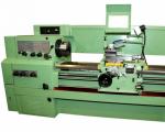
The prerequisites for thread interchangeability and standardization were created by Henry Maudslay around 1800, when the screw-cutting lathe he invented made it possible to cut precise threads. He made the lead screw and nut for his first machine by hand. Then he turned a screw and a nut of higher precision on the machine. By replacing the first screw and nut with new, more accurate ones, he machined even more precise parts. This continued until the accuracy of the thread ceased to increase.
For the next 40 years, interchangeability and standardization of threads took place only within individual companies. In 1841, Joseph Whitworth developed a system of fastening threads which, thanks to its adoption by many English railway companies, became the national standard for Great Britain, called the British Whitworth Standard ( BSW). The Whitworth standard served as the basis for the creation of various national standards, such as the Sellers standard ( Sellers) in the USA, Loewenhertz threads ( Lowenherz) in Germany, etc. The number of national standards was very large. So, in Germany at the end of the 19th century there were 11 carving systems with 274 varieties.
In 1898, the International Thread Standardization Congress in Zurich defined new international standards for metric threads based on Sellers' threads but with metric dimensions.
In the Russian Empire, there was no standardization of threads at the state level. Each enterprise producing threaded parts used its own standards based on foreign analogues.
The first measures to standardize threads were taken in 1921 by the People's Commissariat of Railways of the RSFSR. Based on the German standards for metric threads, he issued tables of norms NKPS-1 for threads used on railway transport. The tables included metric threads diameter from 6 to 68 mm.
In 1927, on the basis of these tables, the Committee for Standardization under the Council of Labor and Defense developed one of the first state standards of the USSR - OST 32.
In the same year, OST 33A was developed for threads according to the Whitworth standard.
By the beginning of 1932, OST for trapezoidal threads was developed based on the modernized American standards Acme ( Acme).
Founded in 1947
Threads by purpose are divided into the following groups:
1. Mounting threads. Designed for fastening parts, usually metric, single-start.
2. Mounting and sealing threads. They serve both to fasten parts and to prevent fluid from escaping, usually pipe threads.
3. Threads for transmitting movement or running, often multi-threaded.
Types of threads on the profile.
According to the type of thread profile, they are divided into:
Metric thread(GOST 8724-81 (ST SEV 181-75) - diameters and pitches and GOST 9150-81 (ST SEV 180-75) - thread profile.
The thread profile is an equilateral triangle. The tops of the screw thread profile are blunted in a straight line by the value of H/8, and the nuts - by H/4. The profile of the depressions often has a rounding radius of H/6. The blunting of the profile is done to reduce the concentration of stresses, increase the durability of the cutting tool. There are threads with a large pitch, called the main one, and with a fine pitch, which has 4 types. Fine pitch threads are used for large diameter threads, for thin-walled parts, where the thread is used for adjustment. It is applied in the range of diameters from 1 to 600 mm. A thread with a large pitch or the main one is designated M with an indication of the outer diameter (for example, M-20), and with a fine pitch, the type of pitch is additionally indicated (for example, M20x2), the thread is a fastener, less often a running one.
Pipe straight thread(GOST 6357-81 (ST SEV 1157-78). The thread profile is an isosceles triangle with a profile angle of 55 0. It is performed with a profile rounding with a radius of r = 0.137 and without gaps at the tops and troughs for good sealing. Designed to connect pipes and pipeline fittings and is a fastening-sealing thread.It is used in the diameter range from 1/8 "to 6". It is an inch thread and is designated G with an indication of the outer diameter (for example, G2").
Trapezoidal thread(GOST 9484-81, ST SEV 639-77 - diameters and pitches and ST SEV 146-75 - thread profile - for a single thread and ST SEV 185-75 - for a multi-start thread). The thread profile is a trapezoid with a profile angle of 30 0 . It is applied in the range from 8 to 640 mm. Serves as a running thread. It is denoted by Tr indicating the outer diameter, the number of starts for a multi-start thread or pitch (for example, T-190x (2x8) or T-190x8).
Thrust thread (GOST 10177-82 or ST SEV 1781-79). The profile is an unequal trapezoid with a profile angle of 33 0 and inclination angles of the profile of the working side 3 0 and non-working side 30 0 . Designed to transfer force in one direction. Also serves as a running thread. It is applied in the range of diameters from 8 to 280 mm. It is designated Pack with an indication of the diameter and pitch (for example, Pack 80x10).
Rectangular thread- currently superseded by persistent or trapezoidal, not standardized. It has less strength, is difficult to manufacture, the formation of a gap during wear, etc.
Round thread - not very common in engineering.
Conical inch and pipe threads used to connect pipelines to parts.
Fasteners.
Fasteners are bolts, screws, studs and nuts. They include pucks. Bolts are used to fasten parts of not very large thickness, it does not require threading into the part. Structurally, they consist of a body with a chopped honor and a head various shapes, usually hexagonal. Conventionally, a bolted connection is depicted in the drawing, as shown in fig. 1.3.
Screws in appearance resemble bolts or are used without a head, they are screwed into the part located last from the head. Conventionally, a screw connection is depicted as shown in Fig. 1.4.
Studs are used in the same cases as screws, but when the material of the threaded part does not provide sufficient thread durability during disassembly and assembly of connections. Conventionally, the connection with a stud is depicted in the drawings, as shown in fig. 1.5.
The listed parts are manufactured with normal and increased accuracy.
The nuts are a hexagon with a height of 0.8d to 1.6d with a threaded inner hole and are used for tightening parts.
Washers are designed to protect the surfaces of parts from damage during tightening. Mounted under a nut or head, depending on what turns. Special washers also perform a locking function.
Fasteners are most often made of steel, but in special designs they can be made of non-ferrous metals. The material of the remaining bolts, screws, studs is conditionally divided into 12 strength classes according to GOST 1759-70. The strength class is indicated by two numbers. The first number, multiplied by 100, indicates the minimum value of the tensile strength σ in MPa, the second, divided by 10, indicates the ratio of the yield strength σ t to the tensile strength, and the product of these numbers, multiplied by 10, is the yield strength in MPa.
For example, strength class 4.8 indicates that the part is made of steel with mechanical characteristics:
σ in = 400 MPa, σ t = 4.8 = 320 MPa and σ t / σ in = 0.8.
Such properties are possessed by steels of the Steel 10 grade.
The material of the remaining nuts and washers is divided into 7 strength classes. The strength class is indicated by a number, which, when multiplied by 100, gives the stress from the test load in MPa. For example, strength class 4 indicates that the nut or washer is made of steel grade St.3, because σ in \u003d 4 * 100 \u003d 400 MPa.
Specifically, the strength classes must be viewed independently in /2/. The strength class is recorded in the symbol of the fastener.
Conditional image of fasteners.
According to the standards, the symbol includes the name of the part, version, thread diameter, fine thread pitch, degree of accuracy and basic deviation of the thread, length of the bolt, screw (without head) or stud, strength class, indication of the use of calm steel, type of coating, coating thickness and GOST for the part. If the execution is ordinary (without holes), the thread is basic, the use of calm steel is not regulated, the product is uncoated, then this information is excluded from the designation. In the manufacture of parts from alloy steels, after the strength class, the steel grade is also indicated.
Designation examples:
Bolt 2 М20х2.6х70.48.С.037 GOST
Bolt M20.6dx70.48 GOST
Screw M12x1.25.8dx40.88.35x.019 GOST
Screw M12.8dx40.43 GOST
Nut М20х2.6Н.2х13.037 GOST
Nut М20.6Н.5 GOST
Methods for locking threaded connections.
There are a large number of ways to stop or protect against self-unscrewing.
They come down to this:
1. Increased friction in the thread or on the end of the nut (lock nuts, spring washers).
2. Rigid connection of the nut to the screw shaft (castell nuts or wire application)
In mechanical engineering, two types of connections are used - detachable and one-piece. The first type is obtained by riveting and bolting, this method is the most common. The second type is obtained with weld, soldering with solder, as well as gluing parts. If the parts are fastened in the first way, special metal threads are used, which come in different types.
Carving on metal
The thread profile of a different material is a section of a plane passing along the axis of the workpiece. The main characteristics include:
- The outer diameter is the dimensions of the tops of the cylinder, as well as the depressions of the inner surfaces. For pipe threads, the diameter is conventionally indicated in inches.
- The inner diameter is a thread parameter that indicates the dimensions of the fit cylinder along the tops of internal threaded profiles, or along the troughs of external connections.
- The pitch is the distance between the sides of two turns lying side by side, which is measured along the axis of the part.
- The profile angle is the value between the sides of the thread profile triangle, which is measured in the axial plane.
- When continuing the sides of the profile, the height of the original triangle is obtained.
Purpose
Threaded profiles are external and internal. They are used for the following purposes:
- reliable fastening of parts of the mechanism at the required distance;
- creating an airtight pipe connection;
- prevent part movement.
Thread types
Cylindrical metal threads are classified by size, position on the surface, number of entries and area of use. In production, there are:
- metric;
- inch ( conventions dimensions in inches);
- metric conical;
- round;
- trapezoidal;
- stubborn.
These types are used in industry to connect parts of various types.
Metric
This type of threaded profile is used for fasteners. As a result of compliance with the technical conditions, it can be used as a chassis. In section, the thread has the form of a triangle with equal sides, the apex angle of which is 55°. It is made with one or more runs to increase the strength of the connection of parts.
In industry, threads are distinguished with sizes from 0.25 mm to 600 mm, with a pitch of 0.25 mm to 6 mm, right and left execution. Fine pitch is used for thin-walled surfaces. The product marking contains the letter M, size, pitch, and also add the number of entries and type of execution.

Metric thread
Inch
This type of thread is used to connect pipes and valves. Applies to metal surfaces and plastics. Dimensions are in inches, in section it looks like a triangle with equal sides with a vertex angle of 55°. Depressions and peaks are removed to prevent chafing of the metal. The size range starts from 3/16 to 4 inches.
Metric conical
This threaded profile is applied to a conical workpiece along the inner or outer surface. By specifications the taper angle is 1:16. It is used in pipe fasteners to create increased tightness. In the drawings, the metric taper thread is marked with MK, then the size and pitch values \u200b\u200bare indicated.
Round
Round threads are used in pipe fasteners, when connecting taps, joints and branches. In the documentation, Kr is marked, after which the nominal dimensional values \u200b\u200bare indicated. At the base and at the tops, a rounded profile with an angle of 30° is produced.
Trapezoidal
This type of thread is considered running. Differs from analogues in the property of self-braking. This characteristic is achieved by the rotational movement of the nut along the shaft, as a result of which increased friction appears. Does not require the use of additional elements to secure parts.
A trapezoidal thread is used to convert rotation to translational trapezoidal. Used in automotive technology, industrial equipment, machine tools, robotics. The movement of the part on the shaft runs smoothly without jerks. Nominal sizes from 8 mm to 640 mm, in increments from 1.5 mm to 12 mm. Tr is marked on the diagrams, and after that the main parameters are indicated.
stubborn
This type of threaded profile is used for equipment on the shafts of which there is an increased axial load. In the section it is a trapezoid with the location of the working side at an angle of 3 °, and the other at an angle of 30 °. Designated with the Latin letter S.

Thrust thread
Advantages and disadvantages of threaded connections
The operational advantages of a threaded connection include:
- Force control in the manufacture of a thread profile on a workpiece.
- As a result of effective self-braking, fixation in the required position occurs.
- Easy assembly and disassembly with available tools.
- Low manufacturing costs.
- Connection types.
- Possibility of fastening of details of the big size.
The disadvantage of a threaded connection is the uneven load along the line of the thread profile. This phenomenon can lead to premature failure of the first coil, as a result of increased operating forces. Also a disadvantage is the effect of self-unscrewing under the influence of vibrations.
Threading
Produced in several ways:
- Cutter and cutting comb. It is carried out on the machine with the necessary cutters, thanks to this, accurate calibrated measuring devices are obtained. It is rarely used due to the low production speed.
- With the help of a rolling die, as a result of rolling along the body of the part, a threaded surface is obtained. It is obtained by extrusion on the workpiece using rollers.
- Threaded connection milling is possible with the use of special tools. The cutter cuts into the workpiece, gradually decreasing by the thread pitch.
- Grinding equipment makes a connection for measuring equipment with high accuracy.
Independently in a garage, you can make an external profile of fasteners, and you should perform the following manipulations:
- Fix the workpiece in a vise, its diameter must correspond to the size of the external thread.
- Pick up the plate and fix it in the holder.
- Using a file, chamfer the workpiece, then coat with oil.
- Carefully lower the die onto the part.
- Slowly turn the tool to wind it up to the mark of the required thread length.
For internal cutting, taps are used and the following manipulations are performed:
- Using reference tables, specify the required drill diameter.
- Fix the workpiece in a vise, use an electric drill to drill a hole. In this case, the tool must be at a right angle. The recess must be made larger than the profile size, taking into account the tap cone.
- Replacing the drill with a countersink, chamfer the surface of the hole.
- The first run is performed with the tool of the first number, lubricating the working surface with oil.
- Two turns of the tap alternate with one in the opposite direction in order to prevent tool breakage and chip discharge.
- Then repeat the run of the tap of the second and third numbers. The numbers are on the tail.
- For an external thread, chamfer the workpiece, install the die on it at a right angle, after lubricating with oil.
- If skewed, cut off and continue threading.
- Before cutting the internal thread, drill a hole while holding the tool perpendicular. Remove the chamfer and lubricate with oil.
- To prevent breakage of the tap, it is not recommended to use machines and equipment for reinforcement.
- In case of breakage of the tool, tools should be used to remove residues from the recess.
To obtain a high-quality fastening, it is necessary to follow the recommendations and rules for threading. The selection of a quality tool will facilitate the task and speed up the process.
Wood carving has existed for many centuries, new directions, types and subspecies of carving appear, but there is no single classification of carving types. We have summarized the classic and new types of carving. House carving occupies a special place in the classification of carving types. It practically concentrates all types and subspecies of thread.
1. House carving: the origins of wood carving can be traced back to ancient times. With the development of the Russian state, the art of woodcarving also develops. Carvings were used to decorate palaces, temples, churches, icons, houses, wooden buildings, interior items, furniture, household items, musical instruments, toys, souvenirs, amulets. The reign of Peter 1 turned out to be favorable for the development of woodcarving in Russia. Under Peter 1, shipbuilding was most developed, since wood in those distant times was the main material for creating the Russian fleet. The bows of the ships were decorated with figures - images of animals and birds - a dragon, an elephant, the head of a lion or a horse. These images symbolized the power, strength and courage of sailors. The skillfully carved prow figure is not only a worthy decoration of the ship, but also, as it was believed, a symbol of good luck for sailors. Such a carving is called ship or baroque. "Coming ashore" wood carving has found wide application in wooden architecture, the manufacture of wooden utensils, in home decoration and various decorations.
House (ship) carving was most developed in the late 19th and early 20th centuries. At the same time, the carving was not of the same type, it was performed using different techniques - which made the decor of the decorated products more figurative, richer and more picturesque.
2. Saw carving: in the second half of the 20th century, saw carving, made with a thin jigsaw file, became widespread in wooden buildings in the countryside and in the city. Of the variety of types of thread - it is the most common and affordable. Saw thread has several subspecies: through, consignment note, openwork. In all subspecies, the background is cut out or removed.
3. Flat thread and its subspecies: the most common, affordable, not requiring special premises and big material costs is a flat-cutting thread and its subspecies.
4. Contour carving: the name itself suggests that in this carving technique a contour, a contour drawing is performed. Contour carving is used to perform not strict geometric shapes, but free patterns, which, as it were, are drawn on the workpiece with a cutting tool. In this case, various lines can be used: straight lines, curves - arbitrary curvature, wavy, spiral, etc.
5. Geometric thread: the main subspecies of a flat-cut thread, which is based on two components - a plane and a recess made on it. It is called geometric because it is based on all kinds of geometric elements - triangles, polygons, circles, rhombuses, squares, ovals. Combining the simplest geometric shapes, you can get an amazing pattern, where every element, every stroke is accurately drawn. Complex elements of carving are formed from geometric figures: ladders, windings, beads, snakes, lights, spikes, various combinations of which with each other create geometric carving motifs, and the combination of motifs forms a geometric ornament.
6. Staple thread: Staple thread is based on a staple notch or staple cutting, shaped like a fingernail. Therefore, bracketed threads are often called nail threads. Staple carving is a kind of flat carving and, in combination with other types of carving, is used to decorate caskets, cutting boards, decorative panels, household shovels.
7. Wrinkled carving: used for finishing and decorating flat carvings. A feature of this carving is the decoration of the surface of the product of the executed motif with wrinkles-rays. Each ray is an acute-angled groove that originates from a center point. From the center, the groove smoothly passes into an extended wrinkle, reaching the greatest width and depth of the outer end of the ray. There is a way to immortality for wood carving: to keep the skill, experience, carving techniques. Teach the young to carve wood. In villages and cities. After all, they build houses from wood, from logs. This is in the traditions of Russians - to build from wood, cut lace on wood, decorate their homes carved platbands, wings. Folk art is a true value. Woodcarving is an integral part of it. Russians must not forget how to cut wood. Creating beauty with your own hands is in the blood of our crafty people.
Used materials and tools
For wood carving, different types of wood are used. The choice of one or another breed depends on the purpose and shape of the decorated product and the type of carving. From deciduous trees, linden is often used for carving. Linden wood is easily and cleanly cut, little prone to cracking and warping. Due to its low hardness, linden is not used to make furniture, so its use is limited to small household items. Alder wood is also easy to cut, warps little, accepts finishes well and imitates other species, such as mahogany. All this makes it suitable for all kinds of work. An excellent material for carving is birch wood. It is harder than linden and alder and is more difficult to cut, but the quality of the carving is better. Birch wood is well stained and finished. Its disadvantages are the ability to easily absorb and release moisture, as well as the tendency to warp and crack, which does not allow it to be used in large products. From birch, you can make overhead carved decorations and details of furniture and other products. For carving on small items - dishes, souvenirs - poplar and aspen wood is used.
Oak has long been used for large decorative carvings and the manufacture of carved furniture. Oak carving is complex and laborious due to the high hardness of the wood and the tendency to chip, but it is very expressive and decorative.
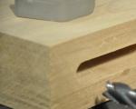
Beech wood is close to oak in hardness, but gives fewer chips, as it is more uniform. Beech is well stained with aqueous solutions of dyes and finished. Beech is mainly used for small carvings. Walnut wood is the best material for carving. It cuts beautifully in all directions, rarely chipping and allows for the most precise carving. Walnut wood is well finished and especially polished. It is used in the manufacture of furniture both for carving on solid wood and for applied carving in combination with other species. For highly artistic small carvings and sculptures, walnut wood is also considered the best material. For small items decorated with carvings, rarer types of wood are also used: apple, cherry, etc. From coniferous species, wood of pine, spruce, cedar, yew is used for carving. From ancient times, decorations for architraves, icons, cornices, and gates were carved from pine. This carving is large, so the unevenness in the density of the layers of early and late softwood does not complicate the work. Spruce cuts lighter than pine, but it has more knots and is very hard, so it is less often used for carving. Harvesting of wood for carving should be done from October to January, when the movement of juices in the trunk stops and the risk of wood cracking and damage by fungi and insects decreases. Boards intended for carving are dried to a moisture content of 8-10%, making sure that cracks and warping do not form. Boards intended for carving are first cut into blanks on circular saws, then they are cut to size on planer and thicknesser machines. Wide blanks are obtained by gluing individual bars or planks with a PVA dispersion. In this case, it is necessary to select wood plots so that the cut and direction of the layers are the same. An incorrectly glued blank made of bars with the opposite direction of the layers of wood makes it difficult for the carver to work, reduces the artistic value of the carving, and when stained with water-based dyes, bars of different shades are obtained. Before carving, the surface of the workpiece is leveled by scraping. The surface is not sanded with sandpaper, as abrasive grains can get into the pores of the wood, which will quickly dull the tool.
Any wood is very sensitive to changes in environmental humidity. This property is one of the disadvantages of timber.
At high humidity, wood easily absorbs water and swells, and in heated rooms it dries out and warps. Drying wood is a very long and troublesome business. It is very difficult to dry hard wood that has a core. Even dead wood after sawing into short logs and barking is covered with numerous cracks. The core is especially valued, the wood of which is harder and drier, and its pores are filled with a special preservative substance. When the ridge dries, the sapwood first cracks, and then the core. To preserve the valuable wood of the core, the sapwood is cut off with an ax and the ends are smeared with putty. Without sapwood, heartwood dries quite well, with almost no cracks. Steaming speeds up the drying of the wood. Raw wood is placed in a vat of suitable size, a little water is poured into the bottom, covered and placed in a heated oven of a gas or electric oven, tightly covering it with a damper. Steamed wood not only resists cracking, but also acquires a deep brownish-golden color. Boiling in oil. Small pieces of wood are boiled in cottonseed oil, drying oil or any vegetable oil.
Cookware made from wood steamed in oil is very water-resistant and does not crack even with everyday use. Boiling in saline speeds up the drying of small pieces of hardwood. Raw wood is placed in a saucepan or boiled water, poured with a saturated solution of table salt and simmered for about 3-4 hours. After that, it is dried at room temperature for about 2-3 weeks. This method is particularly suitable for hardwoods. Drying finished products in sand can achieve an interesting decorative effect. A layer of clean river sand is poured into a suitable container, the product is laid and covered with a new layer of sand. In this case, the product should not touch the walls. After that, a container without a lid is placed on a flooded Russian stove. The drying effect is achieved by the optimal distance of the container in relation to the fire. Drying in grain in Rus' was well known. In the spring, a few weeks before sowing, the workpiece or product was buried in the seed grain, which absorbed moisture from the wood. Then the workpiece was taken out and dried at room temperature.
Drying on cement or concrete floor based on the ability of cement stone to intensively draw moisture into itself. Wet wood is laid on a dry concrete floor and after 2-3 hours it is turned over so that alternately one or the other face is adjacent to the cement floor. Drying in manure, shavings, polyethylene and air is also used.
The natural type of drying is atmospheric, airy. It is necessary to dry the wood in the shade, under a canopy and in a draft. It is better to choose a place for drying at the attic of the house, a barn or a specially arranged canopy. When dried in the sun, the outer surface of the wood heats up quickly, while the inner remains damp. Due to the difference in stresses, cracks form, the tree quickly warps. After atmospheric drying in warm, dry weather, the moisture content of wood is 15-20%. Preparations intended for interior design, can be transferred to a heated room and dried. When drying products, cracks often occur. The best way to seal a large crack is to insert a piece of the same wood into it. If it is impossible to select a piece of wood from the same blank, then a piece of the same color is selected, located far from the core of the trunk and oriented in the same way towards the center. After the glue dries, the junction is planed and cleaned with a planer. Small cracks are usually sealed with sawdust-based putty.
Tools for successful work a woodcarver needs a well-equipped workplace, appropriate tools and fixtures. For the work of cutters, a dry, bright room with a constant temperature and humidity is necessary. The walls and ceiling of the room should be painted in light colors. The equipment of the carver's workplace depends on the nature of the carving work performed. In the manufacture of small products, carving can be done on a regular table. A workbench is suitable for large-sized products.
The workbench or table is placed so that the light falls from the front and left. The best
lighting - natural, without direct sunlight. With artificial lighting, the light should come from two or three sources so that there are no sharp shadows on the workpiece. The workshop needs one carpentry workbench to prepare the material for carving, as well as a grinding machine and a table for sharpening and straightening tools. For woodcarving, various shapes, chisels or chisels are used. Straight chisels with a web width of 3-30 mm are used mainly for cleaning the background in relief carving, sometimes they are used in contour carving. Oblique chisels, also called cutters, are the main tool for making geometric carvings. They are used both when performing rough work (cutting wood with a full blade), and when stripping threads with the tip of a knife. It is desirable to have several knives with different tip shapes: from sharp (30°) to rounded. Cranberry chisels are distinguished by a short blade 2-15 mm wide and a long, curved neck near the blade. The shape of the canvas may be different. They are used when performing high-relief carving, as well as for cutting in hard-to-reach places. Straight cranberries clean the background in relief carving. Semicircular chisels with a web width of 3-
30 mm, depending on the radius of curvature, there are the following types:
Sloping with a large radius of curvature;
Medium or semicircular;
Steep with a small radius of curvature.
This is the main tool for all types of carving, except for geometric, where these chisels are used only for cutting semicircular holes. Corner chisels with a web width of 5-15 mm are used when sampling narrow groove lines. In cross section, the chisel forms an angle of 50-70°. Such chisels can be made in the form of a cranberry. Tserazik chisels with a width of 2-3 mm are close in shape to steep semicircular chisels, but their profile is deeper. Ceraziki is used to cut through narrow veins. Semicircular shavings are used to work on wood in hard-to-reach places. Rasps are used for surface treatment. Chassines are metal rods, at one end of which there are notches in the form of a grid, dots, stars. They are used for chasing the background, mainly in Kudrinskaya carving. In addition to the main cutting tool, the cutter also needs an auxiliary one: a marking tool, tools for drilling, sawing. Auxiliary tools also include:
Mallets for striking the handle of a chisel when cutting out a background, cutting a relief in a large carving;
A brace or drill with a set of drills for drilling holes in slotted threads and drilling deep places in relief;
Jigsaw and files for sawing out the background in a slotted thread.
In addition, the carver may need carpentry tools when preparing parts for carving: planers, jointers, cycles, etc.
The main technological methods and operations of woodcarving
The manufacturing process of carved products can be divided into the following stages:
Project development;
Procurement and preparatory operations;
Direct carving;
Finishing carved product;
The design development phase may include the process of creating an artistic intent and the process of changing or refining some finished sample. This also includes the development of sketches, drawings and the like. Often the carver has to think over the design of the product, the manufacturing and assembly technology, as well as design the necessary devices.
All this also applies to the design stage. Prepared and preparatory operations include, for example, the following types of work:
Wood harvesting;
Drying wood;
Material selection;
Processing of blanks and manufacturing of products for thread;
Marking blanks for threading;
Tool sharpening, etc.
Sketching and modeling: the development of sketches and modeling of future carvings occupy an extremely important place in the carver's robot. Of course, not all people can draw like artists, but often this is not required. In addition, it has been noted that drawing abilities can develop, you just need to show patience and perseverance. At first, in carving, you can get by with ready-made samples, gradually starting to make your own changes and improvements to them. Then, with the accumulation of skills and experience, move on to completely independent works. The carver needs to study the issues of composition and perspective, the techniques of geometric constructions, various types of proportions. To do this, read the relevant literature and get acquainted practically. When performing complex types of carving, one pattern is not enough. Sometimes, to clarify the shape of the relief, the figure shows details in section. However, this does not always help. In such cases, it is recommended to make a model of the future carved product in a material that is easier to process - clay, plasticine, gypsum.
The model makes it possible to feel the volume, to clarify the ratio of details between themselves and with the background, to clarify the carving technique, to determine which tool is needed for work. At home, it is most convenient to use plasticine for modeling - it does not dry out, it is always ready to work, and does not give dirt. The model can be performed in a generalized form, without detailed details. It is enough if it conveys the main, most important elements of the future product.
Enlargement and reduction of the sketch. Quite often, a carver needs to rescale a sketch he has made or an illustration in a book. To do this, the following main methods can be used:
Resizing "by cells";
Redrawing a picture with a pantograph;
Photocopying.
Translation and rescaling of the drawing is very easy to do with photocopying. AT modern conditions this is the cheapest, easiest and fastest way.