Planer s25. Replacement parts and accessories ordered as options
S25-4AB. Four milling spindles of a heavy series machine.
The machine of the heavy series S25-4AB is designed for the production of various molded products and profiled timber, including natural moisture.
Features of the 4-sided 4-spindle machine S25-4AB- The heavy cast bed, which has undergone special processing, dampens any vibrations that occur during processing, and allows you to get high-quality products.
- High-speed spindles of the increased accuracy.
- For the manufacture of feed tables, steel 40X (with chromium) is used to increase wear resistance.
- Distributed feed mechanism with upper and lower feed rollers.
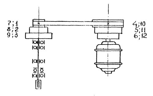
- The feed drive from the electric motor to the module shaft is organized by a pulley on the electric motor shaft and a pulley on the module shaft. Pulleys are 2-stage, 3-strand with the use of common V-belts. The pulley on the shaft of the modules moves freely, which allows you to get 4 permanent gears. In combination with a frequency converter installed in the electrical cabinet and changing the rotation speed of the electric motor, the resulting speed range is from 2 to 40 m/min with a guaranteed broaching of any workpiece.
- The upper feed rollers are equipped with mechanical clamps, which allows processing at low negative temperatures.
- The feeding upper rollers can be equipped with a pneumatic clamping system with continuously adjustable pressure force, which can adjust the pressure separately.
- The upper feed rollers are made with "wolf tooth" corrugation, which ensures the processing of the workpiece of any humidity, with less indentation of the rollers into the wood.
- The table lubrication system is used to reduce the load on the feed mechanism and to pull lumber of natural moisture.
- The machines are equipped with a system of digital indication of the movement of the spindles.
- The aspiration system is purchased at the rate of 2000 m 3 / h per one machine support.
- The machine complies with the current GOSTs and TU for this group of goods, which is confirmed by the presence of a certificate of conformity and marks of the manufacturer.
- The supplied equipment is guaranteed for 12 months from the date of commissioning by the manufacturer or the representative of the plant (dealer).
- The straightness of the base side of the machined workpiece is not more than 0.3 mm over a length of 1000 mm.
- The perpendicularity of the sides of the base face of the processed workpiece is not more than 0.25 mm over a length of 100 mm.
- The uniformity of the thickness and width of the processed sample is not more than 0.3 mm.
Replacement parts and accessories*, ordered as an option (upon request and at an additional cost). You can check the exact price and production time with our managers.
* - the range and quantity of wood cutting tools supplied with the machine is determined according to the supply contract (including cylindrical milling cutters).
Recommended to purchase additional- Soundproof fence. Protection of personnel from noise vibrations - 1 pc.
- Electric motors of 2.3 spindles, 15 kW each. Installation of electric motors of increased power on vertical calipers - 1 set.
- Electric motors 7.5 kW. It is possible to install electric motors of reduced power on any of the calipers - 1 set.
- Wooden packing box - 1 pc.
- Vibration support. Installations on the foundation - 6 pcs.
- Pneumatic clamping system. Simplifies pressure adjustment of pressure rollers. (S25-4AB.70.000) - 1 set.
- The mandrel is collet right. Possibility of mounting a wood cutting tool with a bore diameter of 60 mm on the upper horizontal spindle. (IP.07.000) - 1 pc.
- The mandrel is collet right. Possibility of mounting a wood cutting tool with a bore diameter of 60 mm on the right vertical spindle. (IP.07.000-02) - 1 pc.
- The mandrel is collet left. Possibility of mounting a wood cutting tool with a bore diameter of 60 mm on the left vertical spindle. (IP.08.000-02) - 1 pc.
- Device for removing cutters. Removal of cylindrical wood-cutting mills from spindle shafts. (IP.12.000) - 1 pc.
- Device for installation of knives of combined mills. Installation of knives in wood-cutting cylindrical planing drums with a diameter of 140 mm. (IP.23.000-02) - 1 pc.
- Foundation bolt. If vibration supports are not purchased. (1.1.M20X330. St3 GOST 24379.1-80) - 6 pcs.
| Specifications | S25-4AB |
| Workpiece dimensions, mm | |
| Processing width with horizontal cutters with a diameter of 140 mm | 35-260 |
| Height of processing by vertical cutters 140 mm | 12-230 |
| Minimum workpiece length for in-line processing | 250 |
| Minimum length of a single piece | 700 |
| Minimum product dimensions, mm | |
| Width with cutters 140 mm | 30 |
| Height with cutters 140 mm | 10 |
| Maximum allowance when machining with cylindrical cutters, mm | |
| On the 1st spindle | 8 |
| On 2-4 spindles | 10 |
| Number of spindles, pcs | 4 |
| Spindle speed, rpm | 6000 |
| Profiling depth, mm | |
| On the 1st spindle | 3 |
| On 2-4 spindles | 30 |
| Landing dimensions of horizontal spindles, mm | |
| Length | 260 |
| Diameter | 50 |
| Landing dimensions of vertical spindles, mm | |
| Length | 230 |
| Diameter | 50 |
| Diameter of cylindrical cutters, mm | 125-140 |
| *Diameter of vertical profile cutters, mm | 110-200 |
| Diameter of horizontal profile cutter, mm | 110-200 |
| Feed speed, m/min | 2-40 |
| power, kWt | |
| Electric motor of the 1st spindle | 11 |
| Electric motor of the 2nd spindle | 11 |
| Electric motor of the 3rd spindle | 11 |
| 4th spindle motor | 11 |
| feed drive | 4 |
| lifting-lowering | 1,1 |
| The total power of the machine (rounded), kW | 50 |
| Diameter of outlet nozzles of aspiration, mm | DN150 |
| Productivity of the required aspiration, m 3 / h | 4х2000 |
| Overall dimensions of the machine, mm | |
| Length | 4300 |
| Width | 1500 |
| Height | 2000 |
| Weight, kg | |
| Stanka | 4600 |
* - profile cutters are not installed on the lower support.
Scope of delivery of the four-sided machine S25-4AB- The machine is assembled. (S25-4AB.00.000) - 1 pc.
- Sleeve (possibility of processing narrow workpieces). Installation instead of the left row of feed gear rollers in the direction of the workpiece. (C16-1A.00.028) - 8 pcs.
- Key. Tightening and loosening the nut fixing the tool on the spindle. (IP.16.000) - 1 pc.
- Key. Tightening and loosening the nut fixing the tool on the spindle. Ease of use with the right vertical caliper. (IP.17.000) - 1 pc.
- Ring set. Spacers for horizontal spindle shafts for the possibility of installing wood cutting tools of various lengths. (IP.35.000) - 4 pcs.
- Lever. Movement of calipers in the horizontal and vertical direction. Loosening and tightening the locking screws. (DIN468-160-V17) - 1 pc.
- Key. (7812-1606 D Chem. Ox. prm. GOST 25787-83) - 1 pc.
- Headphones antinoise. (COM 3 GOST 12.4.051-87) - 1 pc.
- Additional support. Machining workpieces with a width of more than 160 mm with a lower horizontal spindle. (C25-4A.12.500) - 1 pc.
- Additional support. Machining workpieces over 160 mm with an upper horizontal spindle. (C25-4A.15.500-02) - 1 pc.
- Manual. (S25-4AB RE) - 1 pc.
The mechanism for feeding blanks is driven by an electric motor (1). The feed drive from the electric motor to the modules shaft is organized by a pulley (2) on the electric motor shaft and a pulley (3) on the splined shaft (4) of the modules (5). Pulleys 2-speed, 3-groove with the use of common V-belts A-1000 III GOST 1284.1-88 (6). The pulley on the splined shaft of the modules moves freely, which allows you to get 4 permanent gears. In combination with a frequency converter installed in the electrical cabinet of the machine and changing the speed of rotation of the electric motor, the total speed range obtained is from 2 to 40 m/min. Tensioning, loosening or rearrangement of the belts is done by removing the guard (7) and turning the threaded screw (8).
Feed speed 7 m/min at 50 Hz (with frequency converter 2-14 m/min).

Feed speed 10 m/min at 50 Hz (with frequency converter 5-20 m/min).

Feed speed 13 m/min at 50 Hz (with frequency converter 6-26 m/min).

Feed speed 19 m/min at 50 Hz (with frequency converter 9-40 m/min).
The four-sided machine S25-5AB is designed for the production of various molded products and profiled timber, including sawn timber of natural moisture.
The machine has a heavy frame that effectively dampens the vibrations that occur during operation, and high-precision dynamically balanced spindles made of heat-treated steel, which are precision machined and controlled, which allows achieving the highest quality of product processing. High wear resistance of the feeding tables is achieved by using chrome-plated steel in their manufacture.
The workpiece feed speed can be varied in the range from 2 to 40 m/min through the use of a frequency converter (stepless speed control) and the use of a movable V-belt pulley system that allows you to set 4 constant speeds. The reliability of gripping and pulling the workpiece of any humidity is ensured by mechanical clamps of the upper feed rollers, which work flawlessly even at low temperatures, as well as by special corrugation of the rollers themselves. Moving and setting in a given position of the machine spindles is carried out according to a system of digital indicators. There is a table lubrication system to reduce the load on the feed mechanism when moving a workpiece of natural moisture.
Optionally, the machine can be equipped with a system of pneumatic clamps for the upper rollers to adjust the pressure and a set for longitudinal sawing of the workpiece.
Finished product quality:
- deviation from the straightness of the base side is not more than 0.3 mm over a length of 1000 mm;
- perpendicularity of the sides of the base plate of the processed workpiece is not more than 0.25 mm over a length of 100 mm;
– uniformity of the thickness and width of the processed sample of the product is not more than 0.3 mm
Technical characteristics of the machine S25-5AB
| Number of spindles, pcs. | 5 |
| Moulder spindle position | bottom |
| Spindle speed, rpm | 6000 |
| Landing dimensions of horizontal spindles, length x diameter, mm | 250x50 |
| Mounting dimensions of vertical spindles, length x diameter, mm | 230x50 |
| Feed speed, m/min | 2-40 |
| Workpiece dimensions with cutters Ø140, mm, width/thickness | 40-260 / 12-230 |
| The minimum length of the workpiece when processing in the stream, mm | 250 |
| Minimum length of a single workpiece, mm | 700 |
| The maximum thickness of the workpiece for longitudinal sawing, mm | 50 |
| Minimum product dimensions with cutters Ø140, mm, width/thickness | 30/10 |
| Maximum allowance when machining with cylindrical cutters, mm | 10 |
| Depth of profiling on the 1st spindle, mm | 3 |
| Profiling depth on 2-5 spindles, mm | 30 |
| Diameter of cylindrical cutters, mm | 125-140 |
| Diameter of profile cutters on vertical spindles, mm | 110-200 |
| Diameter of profile cutters on horizontal spindles, mm | 110-200 |
| Circular saw diameter, mm | 250 |
| Power of electric motors of spindles, kW | 5x11 |
| Feed motor power, kW | 4 |
| Lift motor power, kW | 1,1 |
| Total power, kW | 60,1 |
| Diameter of outlet nozzles of aspiration, mm | 150 |
| Productivity of the required aspiration, m3/h | 5x2000 |
| Machine dimensions, mm | 4800x1500x2000 |
| Dimensions of a cargo piece including packaging, mm | 5000x1720x2330 |
| Machine weight, kg | 5300 |
| Machine weight including packaging, kg | 5500 |
Contents of delivery:
| SYMBOL | NAME | AMOUNT |
| S25-5AB.00.000 | Complete machine | 1 |
| С16-1А.00.028 | Sleeve (possibility of processing narrow workpieces). Installation instead of the left row of feed gear rollers in the direction of the workpiece | 10 |
| С25-5А.11.021-03 | Plate. Mounted on a moulder for profiling | 2 |
| С25-5А.10.011-01 | Video clip. Installed instead of feed rollers for processing narrow workpieces | 2 |
| IP.16.000 | Key. Tightening and loosening the nut fixing the tool on the spindle | 1 |
| IP.17.000 | Key. Tightening and loosening the nut fixing the tool on the spindle. Ease of use with right vertical caliper | 1 |
| IP.35.000 | Ring set. Spacers on spindle shafts to accommodate tools of various lengths | 6 |
| DIN468-160-V17 | Lever. Movement of calipers in the horizontal and vertical direction. Loosening and tightening the locking screws | 1 |
| Key 7812-1606 Chem. Oks. Prm. GOST 25787-83 | 1 | |
| Antinoise earmuffs COM 3 GOST 12.4.051-87. Delivery is carried out during the manufacture of the machine without ZIO, replacement for 14353M is allowed | 1 | |
| C25-4A.12.500 | Additional support (processing of a workpiece with a width of more than 160 mm with a lower horizontal spindle) | 1 |
| С25-4А.15.500-02 | Additional support. Machining workpieces over 160 mm with upper horizontal spindle | 1 |
| С25-4А.15.500-06Н | Additional support. Machining workpieces with a width of more than 160 mm with a molding lower horizontal spindle | 1 |
| S25-5AB RE | Manual | 1 |
Additional equipment:
| NAME | PURPOSE | PRICE |
| Soundproof fence | Protection of personnel from noise vibrations | 120 000 |
| Wooden packing box | 60 000 | |
| Vibration support | Foundation installation | 8x1080=8640 |
| Electric motors 15 kW | Installation of high-power electric motors on the 2nd and 3rd (vertical) calipers | 70 000 |
| S25-5AB.70.000 Pneumatic clamping system | Simplify pressure adjustment of pressure rollers | 120 000 |
| Jointer for 5th spindle | To remove the residual deviation of the knives from the cutting diameter | 90 000 |
| Cutter with hydraulic clamp | Team lightweight 180x50x125 z8 | 26 000 |
The amount of movement of calipers, mm:
Constant feed rates:
| BROADCAST | FEED SPEED | FEED SPEED |
| 1st | 7 | 2…14 |
| 2nd | 10 | 5…20 |
| 3rd | 13 | 6…26 |
| 4th | 19 | 9…40 |
The S25-5AB machine has a certificate of conformity.
The warranty period is 12 months from the date of commissioning by the manufacturer.
The C25-4A four-sided machine is designed for the production of high-quality molded products (lining, floorboard, planed timber, platband, plinth) from edged boards or timber in industrial volumes (up to 2 cubic meters per hour).
Workpieces are processed simultaneously from 4 sides with a constant mechanical feed. The design and power of the machine allows you to process workpieces in a wide range of sizes. The machine bed is cast iron, box-shaped. Four calipers, a drive and a feed mechanism with pressure rollers are installed on the bed.
Steel overhead tables and guide lines with side clamps are attached to the upper plane of the bed. The feed drive, consisting of an e / motor and a variator, allows you to smoothly change the feed rate from 10 to 47 m / min. The machine spindle is designed with increased rigidity using special high-speed bearing units.
Distinctive features of C25-4A:
. Lower drive line.
. High productivity of the machine.
. Exceptionally precise design of 4 high speed spindle units.
. High precision cast iron machine bed.
. The feed rollers are located along the entire length of the workpiece processing.
. The large base of the machine provides excellent geometric dimensions of the product.
. The stepless feed drive allows you to smoothly change the speed of the workpiece.
. High workpiece feed rate.
. Convenient setup and readjustment of the machine.
The dispersed feed mechanism with upper pneumatic and lower feed rollers pulls the workpiece of any humidity.
The feed drive is implemented on the basis of an inverter with a smooth change in speed, which significantly increases the resource of the moving joints of the feed mechanism.
Simplified machine setting by the introduction of digital mechanical reading devices, with an accuracy of 0.1 mm.
The spindle and motors of the machine are precisely dynamically balanced.
Warranty 1 year.
NAME OF PARAMETERS;DATA
Workpiece width, mm: min - max; 50 - 260
Workpiece thickness, mm: min - max; 12 - 230
The smallest dimensions of the processed product, mm: thickness / width; 10/45
The smallest length of a single processed workpiece, mm; 630*
The largest allowance for processing with cylindrical cutters, mm; 7
The greatest depth of the processed profile, mm; fifteen
Workpiece feed rate (stepless), m/min**; 3-22**
Number of spindles, pcs.; 4
Electric motors of horizontal calipers, kW; eleven
Electric motors of vertical calipers, kW; fifteen
Feed drive electric motor, kW; 4.0
Spindle diameters, mm; 50h6
Frequency of rotation of cutters, rpm, not less; 5600
Diameter of cylindrical cutters, mm; 140
Diameter of profile cutters, mm (min - max); 125…203
Overall dimensions of the machine, mm: length x width x height; 3150 x 1315 x 1570
Mass of the machine, kg, no more; 4600
State: new
Delivery: by agreement
Manufacturers of desktop drilling machine S-25:
- Novosibirsk Radiotechnical College
- Kalyazinsky Machine-Building College. Training and production workshops
C-25 desktop drilling machine. Purpose and scope
Table drilling machine "C-25" is a precision machine designed for drilling precise holes in small parts of cast iron, steel, non-ferrous alloys and non-metallic materials in industrial enterprises, repair shops and household workshops.
S-25 machines allow you to perform the following operations:
- drilling
- countersinking
- deployment
- reaming
The main technical characteristics of the S-25 desktop drilling machine (Kalyazinsky Machine-Building College)
Start of mass production - 1953.
- Maximum drilling diameter - Ø 5 mm
- Maximum drilling depth (spindle stroke) - 75 mm
- Distance from the spindle axis to the bed (outreach) - 185 mm
- Spindle RPM Limits - (6 steps) 1600..8000 rpm
- Spindle end - AT 10
- Motor power: 400 Tue
- Machine weight: 128 kg
Spindle C-25 machine receives three rotation speeds from three-stage drive pulleys, which provides a choice of 3 cutting speeds - 1600, 2500, 4000 rpm at engine speed 1400 rpm. At engine speed 2800 rpm spindle speed is - 3200, 5000, 8000 rpm.
The end of the spindle machine S-25- external shortened cone B10 (Morse taper KM1) according to GOST 9953 (Shortened tool cones) - shortened cone: D = 10.094 mm.
A shortened cone B10 corresponds to a three-jaw drilling chuck of the 4th standard size according to GOST 8522 (Three-jaw drilling chucks) with a clamping range of 0.5÷4 mm.
An example of a symbol for a drilling 3-jaw chuck of the 4th size:
Cartridge 4-B10 GOST 8522-79
Morse taper tool shortened
Tool cone - Morse cone - one of the most widely used tool mounts. Introduced by Stephen A. Morse around 1864.
Morse taper is divided into eight sizes- KM0 to KM7 (English: MT0-MT7, German: MK0-MK7).
Standards for Morse taper: GOST 25557 (Tool cones. Main dimensions), ISO 296, DIN 228. Cones made according to inch and metric standards are interchangeable in everything except the shank thread.
For many applications, the length of the Morse taper has proven to be excessive. Therefore, a standard was introduced for nine standard sizes of short Morse tapers (B7, B10, B12, B16, B18, B22, B24, B32, B45), these dimensions are obtained by removing the thicker part of the cone. The number in the designation of the short cone is the diameter of the thick part of the cone in mm.
Russian standard for short cones GOST 9953 Short tool cones.
Russian standard for drill chucks GOST 8522 Three-jaw drill chucks.
- B7- Morse taper KM0, D = 7.067 mm;
- B10- Morse taper KM1, D = 10.094 mm. Cartridge 4-B10(0.5÷4 mm);
- B12- Morse taper KM1, D = 12.065 mm. Cartridge 6-B12(0.5÷6 mm), Cartridge 8-B12(1÷8 mm);
- B16- Morse taper KM2, D = 15.733 mm. Cartridge 10-B16(1÷10 mm), Cartridge 13-B16(1÷13 mm);
- B18- Morse taper KM2, D = 17.780 mm. Cartridge 16-B18(3÷16 mm);
- B22- Morse taper KM3, D = 21.793 mm. Cartridge 20-B22(5÷20 mm);
- B24- Morse taper KM3, D = 23.825 mm;
- B32- Morse taper KM4, D = 31.267 mm;
- B45- Morse taper KM5, D = 44.399 mm.
Where D- diameter of the cone in the main plane.
The C-25 benchtop drilling machine is a precision machine designed for drilling precise holes from 0.5mm to 4mm.
Spindle rotation, assembled on ball bearings, is made from an individual squirrel-cage type electric motor with a 3-stage pulley, so that the spindle can rotate at six different speeds ranging from 1600 to 8000 rpm with a two-speed electric motor 1400, 2800 rpm.
Motor start done with a package switch.
Spindle smooth operation thanks to lightweight, well-balanced aluminum pulleys, an endless flat belt protected by a molded casing with an easy-to-remove cover.
Belt tension carried out by moving the motor together with the bracket.
Upper end of the spindle unloaded from a pulley rotating on individual ball bearings mounted in the machine bed bushing. The lower end is provided with a conical hole for inserting a collet and a thread for a clamping nut.
Drill head includes the entire drive with drilling spindle and feed mechanism. It is set to a height corresponding to the size of the product by means of a screw and nut, and is clamped on the column with a handle.
The limb ring is installed in such a way that when the desired depth is reached, the ring receives a stop and stops the rotation of the roller with the gear.
Spindle feed- manual, produced by means of a sensitive lever, gear and spindle cup.
The drilling spindle, together with the sleeve, is balanced, located in the flange, by an adjustable flat spring, which is in connection with the gear and the lever. To set the spindle to a certain drilling depth, a special collar is used, which is located on the gear shaft, and a stop screw on the bed serves as a limiter.
drilling table It is a rectangular plate with stiffeners and at the same time is the base of the column. The table is equipped with a wide groove for draining coolant and two T-slots for attaching fixtures.
Machine column can be moved along the T-slot, leaving a large support surface for drilling large workpieces with holes lying on the side.
Replacing a normal table with a large one makes it possible to install several columns side by side, and the distance between individual columns can be adjusted as you like.

Photo of the C-25 drilling machine

Photo of the C-25 drilling machine

Photo of the C-25 drilling machine
C-25 Kinematic diagram of a drilling machine
Kinematic diagram of the C-25 drilling machine
The location of the components of the drilling machine C-25

- Work table with column
- Spindle drive
- electric motor
- Drilling head (headstock) with a spindle feed unit and a unit for moving the head along the column

The location of the controls for the drilling machine s-25
- Vertical spindle handle
- Drill head clamp handle on column
- Handwheel for moving the drilling head along the column
- Electrical motor speed switch

Spindle feed unit of the drilling machine s-25

Spindle assembly of the drilling machine s-25

The electrical circuit of the drilling machine s-25
Installation of the drilling machine C-25
The machine is installed on a table. Before tightening the bolts, the machine must be precisely aligned, for which a level is placed on the table along and across. After reconciliation, the bolts must be tightened tightly, observing the level.
Machine start
Before start-up, the machine must be thoroughly cleaned, washed with kerosene, wiped and lubricated, paying special attention to friction surfaces and lubrication holes. After making sure of the correct installation and assembly of the machine, having checked the rotation and movement of units and mechanisms in any direction, the machine starts for a while, to idle, during which the operation of individual mechanisms is checked.
After carrying out the above operations, if nothing is in doubt, the machine is given a load.
Machine adjustment
The clamping of the spindle cup in the bed, the movement of the motor to tension the belt, the installation of the drilling head according to the height of the workpiece and at a given drilling depth are subjected to adjustment.
Control
Turning the machine on and off is done by starting and stopping the motor, using a batch switch.
The change in speed is made by transferring the belt from one step of the pulleys to another with the motor turned off and the cover of the casing removed, guided by the speed table placed on the casing of the machine.
Machine lubrication
The most important parts to be lubricated are the spindle and the spindle cup, which during the operation of the machine are lubricated once a decade by pouring spindle oil No. 2 into the oilers.
The technical vaseline in the ball bearings of the spindle and the spindle pulley is changed once every 3 months.
Technical characteristics of the machine S-25
- С-25 (1) - Novosibirsk Radiotechnical School
- S-25 (2) - Kalyazinsky Machine-Building College
| Parameter name | S-25 (1) | S-25 (2) |
|---|---|---|
| Main parameters of the machine | ||
| The largest nominal drilling diameter, mm | 6 | 1..5 |
| The smallest and largest distance from the end of the spindle to the table | 0..200 | 0..270 |
| Distance from the axis of the vertical spindle to the rack guides (outreach), mm | 125 | 185 |
| Desktop | ||
| Dimensions of the working surface of the table, mm | 220 x 300 | 180 x 500 |
| Number of T-slots Dimensions of T-slots | - | - |
| Spindle | ||
| The greatest movement of the spindle head along the column, mm | 210 | |
| Spindle sleeve stroke, mm | 70 | 75 |
| Spindle speed, rpm | 1600, 2500, 4000 3200, 5000, 8000 |
1600, 2500, 4000 3200, 5000, 8000 |
| Number of spindle speeds | 6 | 6 |
| Spindle taper | B10 (1a) | B10 (1) |
| Drive unit | ||
| Drive motor, kW (rpm) | 0,6 (1400, 2800) | 0,4 (1400, 2800) |
| Motor type | А031-4/2 | AOL 21-2 |
| Dimensions and weight of the machine | ||
| Machine dimensions (length width height), mm | 590 x 400 x 560 | 590 x 450 x 560 |
| Machine weight, kg | 80,5 | 128 |