Network construction plan. Network planning and management. The rule for the sequence of depicting works: network models should be built from beginning to end, i.e. from left to right
Renewables are resources whose energy is continuously restored by nature: the energy of rivers, seas, oceans, the sun, wind, the bowels of the earth, etc.
Non-renewable- these are resources accumulated in nature earlier, in distant geological eras, and in new ones geological conditions practically non-renewable (organic fuels: coal, oil, gas). Non-renewable energy resources also include nuclear fuel.
Fossil fuel energy (thermal, condensing power stations, boiler rooms) has become traditional. However, an assessment of fossil fuel reserves on the planet, taking into account the technical capabilities of their extraction and the rate of consumption due to increased energy consumption, shows the limited reserves. This is especially true for oil, gas, and high-quality coal, which are valuable chemical raw materials that are irrational and wasteful to burn as fuel. The combustion of large quantities of fuel in traditional power plants has a negative impact on environment: pollution, changes in the gas composition of the atmosphere, thermal pollution of water bodies, increased radioactivity in thermal power plant zones, a general change in the heat balance of the planet.
The possibilities of nuclear and thermonuclear energy are practically inexhaustible, but they are associated with problems of thermal pollution of the planet, storage of radioactive waste, and possible accidents of energy giants.
In this regard, there is an increased interest in the use of non-traditional renewable energy sources all over the world. Their nature is determined by processes on the Sun, in the depths of the Earth, and by the gravitational interaction of the Sun, Earth and Moon. Settings
powered by renewable sources have a much lower impact on the environment than traditional streams energies naturally circulating in the surrounding space. The environmental impact of renewable energy installations mainly lies in their disruption of the natural landscape.
Currently, renewable energy resources are used insignificantly. Their use is extremely tempting and promising, but requires large expenses for the development of appropriate equipment and technologies. When focusing part of the energy sector on renewable sources, it is important to correctly assess their share, which is technically and economically justified for use. This task - to evaluate and use the potential of renewable resources, to find their place in the fuel and energy complex - faces the economy of Belarus. Its solution will help mitigate the deficit in the republic’s energy system, reduce dependence on imported energy resources, and contribute to economic stability and political independence.
When planning energy from renewable sources, it is important to take into account their features compared to traditional non-renewable ones. These include the following.
♦ 1. Periodicity of action depending on natural patterns uncontrollable by humans and, as a consequence, fluctuations in the power of renewable sources from extremely irregular, like the wind, to strictly regular, like the tides.
♦ 2. Low, several orders of magnitude lower than that of renewable sources ( steam boilers, nuclear reactors), energy flux densities and their dispersion in space. Therefore, power plants using renewable sources are effective with small unit power and primarily for rural areas.
♦ 3.The use of renewable resources is effective only if integrated approach to them. For example, animal waste and
crop production at agro-industrial enterprises can simultaneously serve as raw material for the production of methane, liquid and solid fuels, as well as fertilizers.
♦ 4.The economic feasibility of using a particular source of renewable energy should be determined depending on natural conditions, geographical features of a particular region, on the one hand, and depending on the energy needs for industrial, agricultural production, and domestic needs, on the other. It is recommended to plan energy for
renewable sources for areas of about 250 km. When choosing energy sources, you should keep in mind their quality.
The latter is estimated by the share of the source energy that can be converted into mechanical work. Electricity has high quality. With the help of an electric motor, more than 95% of it can be converted into mechanical work. The quality of thermal energy obtained from burning fuel in thermal power plants is quite low - about 30%.
Renewable energy sources according to their quality are conventionally divided into three groups:
1.Sources of mechanical energy of fairly high quality:
¾ wind turbines - about 30%,
¾ hydraulic installations - 60%,
¾ wave and tidal stations - 75%. 2. Sources of thermal energy:
¾ direct or diffuse solar radiation,
¾ biofuel with a quality of no more than 35%.
3.The energy source using photosynthesis and photovoltaic phenomena have different quality at different radiation frequencies; On average, the efficiency of photoconverters is about 15%.
The main non-traditional and renewable energy sources for Belarus are hydro, wind, solar energy, biomass, and municipal solid waste.
3.1.Solar energy. Possibility of using solar energy.
There are two known areas of using solar energy. The most realistic option is to convert solar energy into thermal energy and use it in heating systems. The second direction is systems of indirect and direct conversion into electrical energy.
Direct conversion of solar energy into thermal energy.
Solar heating systems can perform a number of functions:
¾ heating air, water for heating and hot water supply to buildings in areas with cold climates;
¾ drying wheat, rice, coffee, other agricultural crops, timber to prevent them from being damaged by insects and molds;
¾ supply the heat necessary for the operation of absorption refrigerators;
¾ desalination of water in solar distillers;
¾ cooking food;
¾ pump drive.
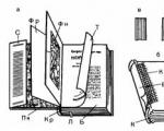
Figure 3.1 shows three of a large number of water heater designs that vary in efficiency and cost.
Fig.3.1. Solar radiation receivers
a) - an open reservoir on the surface of the Earth. Heat goes into the Earth; b) - black tank in a container with a glass lid and an insulated bottom;
c) - a metal flat container filled with water. Standard industrial receiver: heating liquid flows through it and accumulates in a special tank.
To heat buildings in winter, so-called passive and active solar systems can be used. Figure 3.2a shows a passive solar heater: Sun rays fall on the back wall and floor of the building, which are massive structures with enhanced thermal insulation, painted black. The disadvantage of such a direct heating system - a slow rise in temperature on winter days and excessive heat in summer - is eliminated with the help of a storage wall on the sunny side (Fig. 3.2b). The wall works as a built-in air heater with thermal circulation. In summer, such a wall can be shaded by a roof canopy.

Active solar heating systems use external air and water heaters. They can be installed on existing buildings.
In systems of indirect conversion into electricity - at solar thermal power plants, solar energy, similar to the energy of organic fuel at thermal power plants, is converted into thermal energy working fluid, for example, steam, and then into electricity. It is possible to create solar thermal power plants with a capacity of up to several tens - hundreds of megawatts. The concentration of solar energy can be carried out using dispersed collectors in the form of paraboloids with a diameter of more than 30 m.
Fig.3.2 Passive solar heaters:
a - direct heating of the rear wall of the building: massive, black-painted surfaces with enhanced thermal insulation are used to absorb and accumulate solar heat;
b - building with a storage wall.

Fig.3.3 Solar thermal energy storage systems.
a) tower-type solar power plant: 1 - solar boiler; 2 - heliostat; 3 – steam
Each of them independently monitors the Sun and transfers its energy to the coolant. Alternative option - solar power plants tower type. On them, systems of flat mirrors located over a large area reflect the sun's rays onto the central heat sink at the top of the tower (Fig. 3.3).
Unfortunately, the efficiency of converting solar energy into electrical energy at solar thermal power plants is no more than 10%, and the cost of the generated electricity is not comparable with its cost at thermal power plants and even nuclear power plants. A serious problem is the variability of solar radiation throughout the day and its dependence on the time of year. Energy storage is required to provide 24/7 power supply. In this regard, the joint operation of solar thermal and pumped storage power plants is rational.

It is tempting and promising to directly convert solar energy into electrical energy using solar cells (Fig. 3.4), which use the phenomenon of the photoelectric effect. Currently, silicon solar cells are the most advanced. Their efficiency is no more than 15%, and they are very expensive. Two options for implementing the principle of photoelectric conversion have been proposed. First
consists of creating solar stations on artificial Earth satellites equipped with solar panels made of photocells with an area of 20 to 100 km2, depending on the power of the station. The electricity generated on the satellites will be converted into electromagnetic waves in the microwave frequency range, sent to Earth, where it is received by a receiving antenna. The second involves installing prefabricated solar photovoltaic panels in sparsely populated and underutilized desert areas of the Earth.
The territory of Belarus is characterized by a relatively low intensity of solar radiation and its significant change during the day of the year. In this regard, it is necessary to alienate significant areas of land to collect solar radiation, and very large material and labor costs. Therefore, for our republic it is realistic to use solar energy for drying feed, seeds, fruits, vegetables, raising and heating water for technological and domestic needs. As a result, possible savings in fuel and energy resources are estimated at only 5000 cu/year.
1.The essence and significance of the method of network planning and management. Essential elements network graphics.
2. General principles of constructing a network diagram. Network diagram parameters.
3.Analytical and graphical calculation of the network diagram. Network diagram optimization. 4.Planning and management construction industry based on network diagrams.
1.The essence and significance of the method of network planning and management. Basic elements of a network diagram.
Network diagram– a schematic representation of the construction process of one object or a complex of objects, which clearly shows the sequence of work and provides both technological and organizational relationships.
The network planning method helps to establish the dependence of construction duration on completion dates individual species works
The network model allows:
Clearly display the structure of the project and establish the relationship of individual sections;
Forecast critical work;
Use resources more efficiently;
A new approach to accounting and reporting in construction, etc.
Basic elements of a network diagram:
 |
|||
 |
|||
Final
Initial
Fictitious
1.work – manufacturing process, requiring labor costs, material resources, as well as time (solid line with arrow name of work)
Cont., number of work. per shift
2.event– the beginning or end of one or more works. Each event is assigned a number (code). All work is limited to two events. Depicted by circles. An event has a beginning and an end.
3.waiting– this is an organizational or technological break between works that does not require the expenditure of resources, but takes time (for example, natural drying of plaster).
4.addiction(fictitious work) – is not related to the consumption of time resources and is introduced to reflect the relationships between real work. Shown as a dotted line with an arrow
5.way– a continuous line characterizing the duration of work from the initial to the final event in the network schedule. The length of a path is the sum of the durations of the activities located on a given path.
In a network diagram, there can be multiple paths between the start and end events. The path with the longest duration is called critical(indicated by two solid lines), and the activities included in the critical path are critical.
2. General principles of constructing a network diagram. Network diagram parameters.
The network diagram is constructed using certain rules:
1. The direction of the arrows is from left to right. The start event code is less than the end event code.
2. Graphs must have simple form, if possible without intersection of vectors. Most works should be depicted with horizontal lines.
3. There should be no “dead ends” (closed contours) on the graph.
4. There can only be one job between two events.
5. If after finishing two jobs you can start a third one, and after finishing each of them you can start other jobs, then dependencies between events are shown.
6. Events from which no work comes out (except the final one) are not allowed.
Introduction
Chapter I. Concept and essence of network planning and management
1.1. The essence of network planning and management methods
1.2. Elements and types of network models
Chapter II. Practical application of network planning and management models
2.1. Network planning and management methods
2.2. Network diagram
Conclusion
Literature
Introduction
IN modern conditions Socio-economic systems are becoming more and more complex. Therefore, decisions made on the problems of rationalizing their development must receive strict scientific basis based on mathematical and economic modeling.
One of the methods of scientific analysis is network planning.
In Russia, work on network planning began in 1961-1962. and quickly became widespread. The works of Antonavichus K. A., Afanasyev V. A., Rusakov A. A., Leibman L. Ya., Mikhelson V. S., Pankratov Yu. P., Rybalsky V. I., Smirnov T. I. are widely known. , Tsoi T.N. and others.
, , From numerous studies individual aspects
network methods of planning and management, a transition was made to the systematic use of a new planning methodology. In literature and practice, the attitude towards network planning not only as a method of analysis, but also as a developed system of planning and management, adapted for a very wide range of problems, has become more and more widely established.
Over the years of practical use in Russia and abroad, network planning has shown effectiveness in a variety of areas of economic and organizational analysis.
The need to use network planning methods in the study of control systems is explained by the many variety of planning models: graphs and tables, physical models, logical and mathematical expressions, machine models, simulation models. Of particular interest is the network method for the formalized representation of control systems, which boils down to the construction of a network model for solving a complex control problem. The basis of network planning is an information dynamic network model, in which the entire complex is divided into separate, clearly defined operations (works), located in a strict technological sequence of their implementation. When analyzing a network model, quantitative, temporal and valuation
work performed. Parameters are set for each work included in the network by their performer based on regulatory data or their own production experience. In dynamic simulation, a model is built that adequately reflects the internal structure of the system being modeled; then the behavior of the model is checked on a computer for an arbitrarily long time in advance. This makes it possible to study the behavior of both the system as a whole and its. Simulation dynamic models use a specific apparatus that allows them to reflect the cause-and-effect relationships between the elements of the system and the dynamics of changes in each element. Models of real systems usually contain a significant number of variables, so they are simulated on a computer.
Thus, the topic of research into network planning methods is relevant, because The graphical representation not only gives an idea of a complex process, but also allows for a comprehensive study of the project management system.
Based on the above arguments of the relevance and topic of the work, we can formulate the goal of the work - to highlight the methods of network planning and management in the study of socio-economic and political processes.
To achieve the goal, the following tasks were set and solved:
1. An analysis of network planning and management was carried out.
2. The essence of network planning and management methods is revealed
3. The types of network planning and management methods are considered, and the scope of their application is studied.
4. Basics covered practical application network planning and management methods.
The subject of my research course work is a methodology for network planning and management.
The object of my course work is the scope of application of the methodology of network planning and management.
Chapter I . The concept and essence of network planning and management
1.1. The essence of network planning methods
Network planning is a set of graphical and calculation methods of organizational activities that provide modeling, analysis and dynamic restructuring of the plan for the implementation of complex projects and developments, for example, such as:
· construction and reconstruction of any objects;
· carrying out research and design work;
· preparation of production for product release;
· rearmament of the army.
A characteristic feature of such projects is that they consist of a number of separate, elementary works. They condition each other in such a way that some work cannot be started before some others are completed.
Main target network planning and management - reducing project duration to a minimum.
Task network planning and management is to graphically, visually and systematically display and optimize the sequence and interdependence of works, actions or activities that ensure the timely and systematic achievement of final goals.
To display and algorithmize certain actions or situations, economic and mathematical models are used, which are usually called network models, the simplest of which are network graphs. With the help of a network model, the manager of a work or operation has the opportunity to systematically and on a large scale represent the entire progress of work or operational activities, manage the process of their implementation, and also maneuver resources.
In all network planning systems, the main object of modeling is a variety of complexes of upcoming work, for example, socio-economic research, design developments, development, production of new goods and other planned activities.
The SPU system allows:
· form calendar plan implementation of a certain set of works;
· identify and mobilize time reserves, labor, material and financial resources;
· manage a set of works according to the “leading link” principle with forecasting and preventing possible disruptions during the work;
· increase the efficiency of management as a whole with a clear distribution of responsibilities between managers different levels and performers of work;
· clearly display the volume and structure of the problem being solved, identify, with any required degree of detail, the work that forms a single complex of the problem resolution process; identify events that are necessary to achieve specified goals;
· identify and comprehensively analyze the relationship between the works, since the very methodology for constructing a network model contains an accurate reflection of all dependencies determined by the state of the object and the conditions of external and internal environment;
· widely use computer technology;
· quickly process large amounts of reporting data and provide management with timely and comprehensive information about the actual state of program implementation;
· simplify and unify reporting documentation.
The range of application of SPU is very wide: from tasks related to activities individuals, to projects involving hundreds of organizations and tens of thousands of people.
The network model is a description of a set of works (set of operations, project). It is understood as any task for which it is necessary to carry out sufficient a large number of various actions. This can be the creation of any complex object, the development of its project and the process of constructing project implementation plans.
The use of network planning methods helps reduce the time required to create new facilities by 15-20%, ensuring the rational use of labor resources and equipment.
The most effective areas of application of network planning and management methods are the management of large targeted programs, scientific and technical developments and investment projects, as well as complex sets of social, economic, organizational and technical measures at the federal and regional levels.
1.2. Elements and types of network models
Network models consist of the following three elements:
· Job (or task)
· Event (milestones)
· Communication (addiction)
Job ( A activity)- this is a process that must be performed to obtain a certain (specified) result, which, as a rule, allows one to proceed to subsequent actions. The terms “task” and “work” may be identical, but in some cases tasks are usually called the performance of actions that go beyond the scope of direct production, for example, “Examination of design documentation” or “Negotiations with the customer.” Sometimes the concept of "task" is used to display work at the lowest level of the hierarchy.
The term "work" is used in a broad sense and can have the following meanings:
· actual work, that is labor process, requiring time and resources;
· expectation– a process that requires time but does not consume resources;
· addiction or “dummy work” - work that does not require time and resources, but indicates that the possibility of starting one task is directly dependent on the results of another.
Section VI.
NETWORK MODELING OF CONSTRUCTION PRODUCTION
147. What are the disadvantages of line graphs?
Line charts are easy to use and clearly show progress construction work. However, they cannot reflect the complexity of the simulated construction process and therefore have the following disadvantages:
– the calendar schedule is static: it does not reflect the entire dynamics of the construction process and needs constant adjustment. But while it is being adjusted, agreed upon and approved, new changes occur as a result of which the revised schedule again does not reflect the actual state of affairs;
- using a linear schedule, it is difficult to determine how construction is progressing at the moment - ahead or behind, and for how long;
– using a linear schedule, it is difficult to determine how the failure to complete one or more works affects the performance of other works, and for how long;
- on calendar schedule the work that determines the construction timeframe is not highlighted; the role of secondary work is not visible, as a result of which the construction management is forced to disperse its attention on all the work, without concentrating it on the decisive areas of the construction;
– a linear schedule does not make it possible to predict the course of events at a construction site, which makes it difficult for the construction manager to choose the right decision for subsequent work.
148. What is a network diagram?
A network schedule is a graphical representation of the technological sequence of work at a facility or several facilities, indicating their duration and all time parameters, as well as the total construction period.
Construction management should be based on a pre-developed model of the production process of construction and installation work, beginning with preparatory work and ending with the commissioning of the facility.
149. What are the distinctive features network diagram in comparison with linear and cyclogram?
Distinctive features of the network diagram are:
– the presence of a relationship between the work and the technological sequence of its implementation;
– the ability to identify work, the completion of which primarily determines the duration of construction of the facility;
– the ability to select options for the sequence and duration of work in order to improve the network schedule;
– facilitating control of construction progress;
– the ability to use computers to calculate schedule parameters when planning and managing construction.
150. What elements does a network diagram consist of?
A network schedule consists of four elements: work, events, expectations, and dependencies.
151.
What does "work" mean?
Work is a technological process that requires time, labor and material resources and leads to the achievement of a certain planned result. Work on the schedule is indicated by a solid arrow, the length of which may not be related to the duration of the work (if the schedule is not made on a time scale).
152.
What does the term “event” mean?
The fact of the completion of one or more works that are necessary and sufficient for the start of subsequent work is called an event. This means that the event takes place instantly, so it does not require any time, material or labor costs. An event is depicted as a circle, inside which a specific number is indicated - the event code.
153. What types of events can there be?
Events can be initiating, terminating, beginning, and ending.
The initial event begins the construction of an object and has no previous work. This event begins the development of the network diagram.
The final event has no subsequent activities and ends the activities in the network diagram.
Events limit the work in question and in relation to this work they can be initial and final.
The start event for the work in question determines the beginning of this work and is the final event for previous works.
The final event determines the completion of this work and is the initial event for subsequent works.

154. What does the concept of “expectation” mean?
In construction, there may be a need for breaks between work performed. Such breaks can be technological and organizational.
Technological interruptions may be associated with the need to strengthen the concrete, harden the screed for roll roofing, dry the plaster before painting, etc.
Organizational breaks may occur when teams are busy necessary professions at another site, waiting for the warm season to carry out landscaping work, etc.
Such technological breaks are called waiting. Waiting is a process that takes time and does not consume material and labor resources. Waiting is depicted, like work, by a solid arrow indicating the duration and name of the wait.
155. What does the concept of “dependency” mean?
There may be technological dependencies between certain types of construction and installation work (for example, finishing work, installation technological equipment in the absence of a roof, landscaping work without laying underground communications and so on.).
Dependency (sometimes also called fictitious work) reflects the technological or organizational relationship of work. Addiction requires neither time nor resources; it determines the technological sequence of events.
The dependency is represented on the network diagram by a dotted arrow.
The dependence can be technological (shows the necessary sequence of work) and resource or organizational, related to the transition of teams or transportation construction machines from object to object.
156. What is the concept of “path” in network graphics?
Each job in the network schedule has its own duration, calculated on the basis of the volume of work to be performed. Having passed from the initial event to the final one, sequentially, along the chain of work and dependencies, you can calculate the total duration of work in each chain.
A path is a continuous sequence of activities in a network diagram. The length of the required path in time is determined by the sum of the duration of the work that makes up this path.
In a network diagram, there may be several paths between the initial and final events, varying in duration.
157.
What is the full path of a network diagram?
The path from the initial to the final event of a network diagram is called complete. The section of the path from the initial event to this event is called the preceding one, and the path from this event to any subsequent event is called the subsequent path.
158.
What is the critical path in a network diagram?
The critical path of a network diagram is the complete path from the initial to the final event, which has longest length(duration) from all complete paths. Its time length determines the deadline for all work in the network schedule.
There can be several critical paths in a network diagram.
Increasing the duration of activities on the critical path increases the total duration of activities; Accordingly, the reduction of these works leads to an overall reduction in the construction period of the facility.
The critical path on the network diagram is highlighted with a thick line or in some other way.
159. What is a critical zone in a network diagram?
A path whose length is slightly less than the critical path is called subcritical. When the duration of work on the critical path is reduced, the subcritical path may become critical.
The combination of critical and subcritical paths forms a critical zone in the network diagram. Identification of a critical zone in the network schedule allows us to identify work that needs to be paid attention to if it is necessary to reduce construction time, either when designing the network schedule, or when monitoring the progress of construction.
160. What is a job code?
In a network diagram, each activity is located between two events (the initial one, from which it leaves, and the final one, which it enters). Each event has its own number, so each work acquires its own code, consisting of the numbers of its initial and final event.
161. What are the basic rules for constructing a network diagram?
There are certain rules for constructing a network diagram:
– for the convenience of constructing a network diagram, the direction of the arrows should be taken from left to right, avoiding, if possible, intersection of lines;
– each work must have its own code. In the case of parallel work that has a single beginning and end, it is necessary to enter additional events, otherwise various works will receive a single name;

– in the network diagram there should be no “dead ends” (events from which no work comes out) and “tails” (events from which no work is included);

– numbering (coding) of events must correspond to the sequence of work in time, i.e. preceding events are assigned lower numbers;
– numbering of events should be done only after the network has been fully constructed and you are convinced that the technological network is built correctly;
– the initial version of the network schedule is built without taking into account the duration of the work that composes it, providing only a technological sequence (in this case, the length of the arrows does not matter).
162. What does the concept of “time reserve” mean?
By comparing the length of the critical path with the length of any non-critical path, we establish that it is possible to increase the length of non-critical work for a certain amount of time without increasing the total construction period of the facility. These days constitute the time reserve, which can be private or general.
163. What is private time reserve?
The private work time reserve is the amount of working time by which the duration of this work can be increased or its start postponed so that the early start of subsequent work does not change.
164. What is the total reserve time?
The total (full) time reserve is understood as the amount of working time by which the duration of a given job can be increased, provided that the duration of the longest path passing through this job does not exceed the length of the critical path.
165. Why is a calendar ruler used when developing a network diagram?
When developed, a network diagram is a non-scale model, but there is a need to present it in a familiar form on a time scale, accessible for use at any level of management. To link the schedule to calendar time, a calendar ruler is used. By linking network schedule events to a calendar, you can clearly see when what work is being done and when it should be completed.
A large-scale schedule is usually built based on the early dates of events.
166. How to determine the earliest possible date for an event to occur?
An event that includes one work can be started when the event of the previous work has occurred and the work of the event in question has been completed.
If the event in question includes several jobs, then it is possible to start the next job only when the longest job included in this event is completed. Having data on the duration of each work included in this event, it is possible to determine for this event the earliest possible date for its completion.
The earliest possible time for an event to occur is equal to the earliest start of the previous event and the duration of the longest path preceding this event.
167. How to determine the latest acceptable time for an event to occur?
If the job in question has one subsequent job, then its late finish is equal to the late finish of the subsequent job minus the duration of the job in question.
If the job in question has two or more subsequent jobs, then its late completion will be the minimum of the difference between the late finishes of subsequent jobs and their duration.
168. For what purpose is a “determinant card” of the network diagram being developed?
The network diagram identification card is the source document for calculating the network diagram. Using the identification card, the duration of each work is assigned based on accepted methods of work production, and the composition of the team and shift are assigned.
169. What data is needed to draw up a network diagram identification card?
The initial data for developing a network diagram identification card (Fig. 4) are:
– the exact name and composition of each work;
– data on available in construction organization brigades and their compositions;
– information about the labor productivity achieved by these teams;
– delivery data building materials and structures, equipment;
– information about existing regulatory documents(SNiP, ENiR, instructions and guidelines for the performance of work);
– data on the mechanisms available to construction and installation organizations.

Rice. 4. Card identifying the works and resources of the network schedule
170. How to determine the duration of work?
Having determined the complexity of the work, you can determine the duration of the work in two ways:
- having assigned the size of the team, divide the labor intensity of the work by the number of workers in the team;
- having assigned the duration of work in days, divide the labor intensity of the work by its duration; in this case we will know the required size of the brigade.
But these provisions do not apply to the implementation mechanized work. In this case, it is necessary to determine the required number of machine shifts of work and, dividing by the number of mechanisms and their shifts, obtain the duration of work in days; In accordance with ENiR, we appoint the composition of the installation team.
171. How are network diagrams “stitched” together?
For certain types of construction and installation work, local schedules can be developed, which must be combined into a single network schedule for the construction of buildings and structures.
In connection with this, it is necessary to link related work (this is the so-called “stitching” of the schedule). This linking must be made using boundary events, i.e. events that are common to different local schedules and occur as a result of the completion of work included in these schedules.
172. How to construct diagrams of labor and material resources?
As a result of calculating the network parameters and the possibility of linking it to the calendar, it is possible to identify the need for labor and material resources at each moment of construction of the facility. To do this, a diagram of resource requirements is constructed, the horizontal vector of which is tied to the calendar, and the vertical vector indicates the amount of resources consumed. The basis for constructing the diagram is the constancy of resource expenditure when performing each job. Adding up the needs of work vertically within a certain calendar period provides the necessary information.
In order to correctly link the network to the calendar, the start dates of a particular work must correspond to the early starts of work, located in the left sector of events.
Works that have a time reserve should be highlighted on the network diagram (on the graph they may have a dashed line in the part of the work where there is a private time reserve), and only that part of the work where there are resources is projected onto the diagram (Fig. 5 and 6 ).

Fig.5. An example of calculating a network diagram directly on the diagram

Fig.6. Construction of a network diagram on a time scale and a diagram of the movement of labor (the number above the arrow is the number of people employed in this work)
173. For what purpose is the network schedule adjusted?
The first stage of developing a network diagram ends with the calculation of its parameters, determining the duration of the critical path and its trajectory. However, the initial (rather, initial) version of the schedule is rarely immediately optimal. Most often, the network has to be adjusted, bringing it into line with the regulatory or directive deadline for the construction of the facility, with the resources available to the performers (labor, material, necessary mechanisms).
After receiving the first version of the network diagram with the definition of the critical path, the calculation of time parameters for each job and the determination of time reserves, the network diagram needs to be analyzed.
By adjusting (optimizing) the network schedule we mean making possible changes to its original version in order to achieve beneficial results and bring the schedule parameters to the indicators for which the network is planned.
To make these amendments, it is necessary to find the most profitable and possible technological solutions, and sometimes design decisions related to reducing the period of construction and installation work or changing the technological sequence of their execution.
Adjustments to the network schedule can be made based on specified construction time frames, labor and material resources, and other necessary indicators.
174. How is the network schedule adjusted over time?
If the initial version of the network schedule has a critical path that does not exceed the established target construction period, then such a schedule can be considered optimal and recommended for execution.
In cases where the critical path in the initial version of the network schedule exceeds the established construction time, it is necessary to adjust the schedule according to the “time” indicator in order to reduce the critical path period.
You can shorten the critical path in the following ways:
- redistribute labor resources from non-critical work to critical work, as a result of which the duration of non-critical work may increase within the available time reserves, and critical work will be reduced;
- attract additional labor and material resources to perform critical work;
- revise the network topology (change the technological sequence of work); increase the number of captures; carry out separate construction and installation operations, where technology and safety of work allow in parallel);
- change, if possible, design solutions in order to reduce construction duration (increase the factory readiness of structures, conveyor-block installation of coating structures, use prefabricated structures instead of monolithic ones, etc.).
Network diagram is a network model reflecting the technological and organizational relationships of the construction and installation work process, with calculated time indicators. Displayed as a graph consisting of arrows and circles. The construction is based on the concepts of “work” and “event”.
Management responsiveness
Accounting for external work
Accounting for resource perspectives
Easily corrected situation
Peculiarities:
The presence of a relationship between the work and the technological sequence of its implementation
Based on the schedule, it is possible to identify work on the execution of which on time depends on the duration of the entire construction
Possibility of variant development
Makes it easier to make adjustments without changing the end result
Essential elements:
Work is the process itself, which requires time, material resources and leads to the achievement of certain results.
Waiting is a process that requires only time (technological and/or organizational break)
Dependency – is entered to reflect the relationship of work (arrow with a dashed line)
Event – the actual completion of one or more jobs, necessary and sufficient for the start of the next job
Path – a certain sequence from one event to another
The critical path is the complete path that has the greatest length (duration).


№16 Basic provisions for organizing the material and technical base of construction
Material and technical base of construction (MTB) - System of enterprises for the production of construction. materials, parts and structures, enterprises for operation and repair of construction. machines and transport, stationary and mobile production plants, energy and storage facilities, construction. organizations, research, design and other institutions and farms serving construction.
The supplier of tools for construction is the mechanical engineering industry. Materials, products, structures for construction are supplied by the enterprises: construction. industry, i.e. enterprises in the construction industry that are on an independent industrial balance sheet or structure balance sheet. organizations in the building materials industry and other industries - metallurgical, chemical, forestry and woodworking, etc.
Sources of supply MT supply for construction is carried out under direct contracts with manufacturers or through a diverse network of intermediary trade organizations. Construction industry enterprises include factories and sites for the production of prefabricated concrete and reinforced concrete structures (except for enterprises subordinate to the building materials industry); factories and workshops for construction and technological metal structures, electrical and sanitary equipment, fittings and embedded parts for monolithic reinforced concrete; factories and shops of commercial mixtures. In a construction trust, a distinction should be made between production and production and assembly bases. The first is intended for the manufacture of materials and structures, the second is for increasing the factory readiness of materials and components. With small production volumes, the CMO has a single production and assembly base, and with large industrial scales. activities, both components of the base are separated into separate structures.
Prom. enterprises construction organizations (on-site, local) are intended to supply construction sites remote from the main base. These include small testing grounds (shops) for concrete reinforced concrete products, stationary and mobile installations of commercial mixtures, mechanical repair shops and vehicle fleets.
Wholesale trade of materials and materials is carried out through wholesale bases, commodity exchanges, and wholesale fairs.
Territorial supply bases carry out wholesale purchases and deliveries of all resources needed by construction organizations, as a rule, on the basis of long-term direct contracts.

Wholesale and retail stores serve as the main source of supply for individual developers and small construction organizations.
Cost of materials and equipment:
1. purchase price;2. shipping cost;3. storage cost;4. cost of shortages and losses.
SUPPLY CYCLE:
1. Determination of needs during the design and budgeting period. 2. Development of design characteristics required for a particular product, part, structure. 3. Calculation required quantity elements and specification preparation. 4. Drawing up an application indicating the requirements. 5. Request for proposals for supply indicating the price or by organizing a tender. 6. Receipt and consideration of proposals. 7. Issuing a purchase order, concluding a supply agreement, subcontracting or leasing. 8. Preparation and submission by the seller or subcontractor of shop drawings or samples. 9. Review and approval of submitted RFs or samples by the contractor and the owner's representative (architect or engineer). 10. Manufacture of the product by the seller or subcontractor. 11. Packaging, delivery and inspection of delivered products. 12. Acceptance or refusal of acceptance by the owner (or his representative), issuance of guarantees in case of acceptance, making necessary corrections. 13. Storage and preparation for use on the construction site. 14. Preparation for installation, installation and testing in the design position.
Not all types of supplies require the sequence listed above. Having issued, for example, an order for the supply of ready-mixed concrete mix, all you need to do to receive the next batch is call the supplier. At the same time, order complex equipment using, for example, intermodal transport, including, for example, sea freight, may require a more complex process than those listed above.
Supply scheduling. Supply is a system interconnected with planning work and monitoring its execution. There are several technical approaches to solving this problem.
The first is to include the stages of the supply process in overall plan works, CP or SG. The difficulty with this option is that a detailed display of all the steps (14 or more) to provide even a limited set of resources will dominate the schedule and make it difficult to read.
The second approach is to develop a separate supply schedule, but linked to the timing of construction and installation works, the so-called modular schedule (manually or on a computer). For example, in the SG of the construction of an object, the need for delivery by a certain date is indicated by one event or one job “Delivery of a set of doors”, in which all the steps to provide this resource are hidden. Only an early (or late) date can be indicated. A detailed schedule indicating each step should be developed separately in the form of a CP or SG, or in the form of a matrix on paper or in electronic form, listing the product, supplier, cost, start and end of each step before putting it into action, early start of work and time reserve between delivery to the work site and the launch site. But even with the best organization, situations may arise that require corrective action, for example, if some material is required earlier than was provided for according to the agreed schedule. This is where experienced agents play a critical role in finding ways and means to keep construction on schedule. Such alternative solutions could be: attracting additional suppliers, changing delivery methods (instead of rail transport, road, air, etc.).
Ideally, a well-organized flow of materials should ensure that vehicles are supplied for loading directly to the point where it is needed and at exactly the appointed time.
Acceptance of material resources, one of the most important operations in the construction supply process, is carried out by carefully checking the quantity, completeness and quality of incoming products, as well as registering them with the appropriate accounting documentation in the prescribed manner. Compliance of all materials, products, structures and equipment with the requirements of state standards (GOCT), technical specifications (TU) and design documentation is mandatory to ensure the quality of construction products and the durability of buildings and structures.
Accounting and control in supply is achieved by recording the availability, receipt and expenditure of material resources using the current document system. In order to have reliable information about the availability of certain resources, it is necessary to promptly prepare and submit to the accounting department of the construction organization primary accounting documents, receipt and expenditure orders, invoices, invoices, etc. The use of material and energy resources is systematically monitored by submission of statistical reports on their expenditure to higher subordinate bodies.
The release of materials for construction and installation works must be carried out on the basis of a limit system. This system is based on a preliminary calculation based on design estimates and approved consumption standards for the amount of materials required for the construction of the facility. These data are employees of the production and technical department construction department are entered into a limit card, which is a single primary accounting document regulating the release of materials from the beginning to the end of the construction of a given facility. The release of materials in excess of the established limit is permitted only with the permission of the chief engineer of the construction department. Obtaining such permission is associated with checking the reasons for overestimating the limit and, if necessary, recovering from persons who allowed an unreasonable overexpenditure of material.
№17 Organization of production and technological equipment for construction
Technological kitting is the process of synchronous complete provision of objects under construction with prefabricated structures, parts, semi-finished products and materials in strict connection with the pace and technological sequence of work.
The fundamental difference between the procurement bodies and the supply bodies operating in most construction organizations is that the procurement management is a combined body, the activities of which combine three main functions of material support: supply, processing, procurement:
1 supply activity consists of obtaining all material resources, regardless of sources of receipt;
2 industrial activity consists of processing materials and products for preparation for direct use in construction work and the production of non-standard and non-serial structures, parts and semi-finished products;
3, the supply of materials and products consists of their centralized delivery for construction in accordance with the approved work schedules, as the final stage of material support for construction.
The kit places a special requirement on the delivery method, which can be formulated as the principle of unloaded delivery of material to the workplace area.
Bagging
Containerization (and, as a consequence, the introduction of heavy-duty containers to reduce transport costs)
Unified normative and technological documentation for packaging ( UNTDK) construction projects as part of the PPR - this is a set of documents that are a project for the technological configuration of the facility. UNTDK is carried out during the period of preparation for construction for the entire facility as a whole or for the volume of work for the planned year. Taking into account the decisions made in the PPR ensures synchronization of the procurement process with the work schedule. The binding of a standard UNTDK to local conditions or development for an individual object is carried out in the departments of preparation for the production of work of the construction organization or on the order of construction organizations by specialized firms in the technological design of construction. The development of UNTD is associated with the formation of technological, supply, installation and flight kits.
UNTDK is one regulatory framework planning:
1. logistics;
2. manufacturing products and increasing the construction readiness of products in industrial divisions of the SMO;
3. organizing the procurement process, including centralized delivery of resources to the work area.
The initial data for developing the UNTDK system are:
1 design documentation;
2 main PPR decisions regarding the sequence and technology of work execution (CP and technological sections);
3 current standards for the consumption of material resources;
4 information about suppliers, means of transport and container fleet.
Types of kits:
Technological (SC, products, etc., necessary to perform a certain set of works)
Delivery (delivered from 1 plant to the site in accordance with the timing and technology)
Assembly (designed for assembling the assembly unit)
Trip (part of the assembly supplied on 1 vehicle - for 1 trip)
The principle of constructibility: the composition of the equipment is formed so that it is a necessary and sufficient part to ensure the spatial stability of the building and its parts.
The principle of manufacturability: the totality of the kit’s resources ensures the continuity of work in accordance with the PPR
Composition and sequence of development of NTDC
The contents of the UNTDK include the following documents:
1. object details card;
2. schemes for the formation of technological kits;
3. assembly and technological maps; (composition and timing of the formation of kits in accordance with the work schedule; carried out on CL, CM, CD, reinforcement, concrete, etc.)
4. summary complete technological map;
5. table of cost of technological kits;
6. standard schedule for completing the facility by suppliers;
7. transport picking schedule; (included in the UNTDK only when mounted “from wheels”)
8. calculation of steel and concrete;
9. technological maps for increasing the construction readiness of products and materials.
The completion and technological map (CPC) is the main document of the UNTDK, which determines the composition and timing of the formation of kits in accordance with the work schedule.
№18 Organization and operation of a fleet of construction machines
Integrated mechanization is a method of fully mechanized execution of certain technological processes in construction, carried out by one or more machines. For a large number of operations, the use of a set of machines significantly increases productivity.
CALCULATION OF THE NEED FOR CONSTRUCTION MACHINERY
At the PIC stage, calculations are performed according to standard indicators to determine the need for construction machinery for 1 million rubles. estimated cost of construction and installation work. The requirement standard includes the main types of construction machines to perform work on the own resources of construction organizations, and also takes into account the needs for machines of manufacturing enterprises that are on the construction balance sheet.
At the PPR stage, the need for construction machines is determined based on the physical (estimated) volumes of work to be performed in one of two ways:
1 according to the norms of machine time consumption of SNiP (Part IV “Estimated norms”);
2 according to machine production standards established by the relevant departments, taking into account local construction conditions.
ORGANIZATIONAL FORMS OF OPERATION OF THE CONSTRUCTION MACHINERY PARK
The forms of organization and structure of the construction machinery fleet depend on the form and structure of the construction and installation organization it serves, the types and volumes of work performed, and are determined by the degree of territorial concentration of construction. The listed factors predetermine the possibility of specialization of operating organizations and influence the depth of its development.
Form I - construction machines are on the balance sheet of construction organizations (SMU, PMK, etc.). The maintenance and operation of the machines is managed by the chief mechanic service. Based on requests from line workers, machines are allocated to sites.
Form II - construction machines are part of and on the balance sheet of specialized mechanization units subordinate to construction organizations. Operational management of the distribution and use of equipment and all payments for its operation are carried out by the CMO. Construction departments receive machines on a service, lease or contract basis. Calculations are made at planned prices.
III form - construction machinery and equipment are part of and on the balance sheet of former mechanization trusts or independent mechanization enterprises subordinate to territorial construction associations, plants, etc. The concentration of construction equipment in specialized mechanization enterprises creates the most favorable conditions for its maintenance and service, ensures the ability to maximize the use of machines in accordance with their technical parameters, and also allows you to concentrate, if necessary, a large number of machines in the desired direction.
IV form - leasing of construction machinery and equipment They are on the balance sheet of leasing companies specializing in leasing (renting) their equipment for short-term or long-term use on a contractual basis.
V form - construction equipment is in the possession of an individual private entrepreneur.
1. Mechanization Department
2. Construction mechanization trusts
3. Means of small-scale mechanization
FORMS OF CALCULATIONS AND RELATIONSHIP OF CONSTRUCTION ORGANIZATIONS WITH MECHANIZATION DEPARTMENTS
In the system of relationships between machine operators and builders, the forms of payment are of decisive importance. The amount of work performed by machine operators for builders can be determined in various ways:
according to the volumes actually completed and according to the time the machine was at the disposal of the construction organization at the site.
1. When calculating the actual work performed, natural indicators of the volume of work are taken as the unit of measurement.
2. Calculation based on machine operating time (per time worked). In cases where accurate recording of the volume of construction work performed is impossible or difficult.
CONSTRUCTION MACHINERY PERFORMANCE INDICATORS
The condition for increasing annual output is the commissioning of a listed fleet of machines. This depends on the operational readiness of the machines, the scope of work and the shift.
The quality of park operation is characterized by a number of specific indicators.
Construction vehicle fleet utilization rate over time k n
Machine utilization rate over time k. mung bean
Machine utilization rate by productivity k np
Machine shift coefficient k.cm
Machine utilization rate over time during a shift kusp.cm
№19 Indicators characterizing the degree of mechanization of construction and installation work. Vehicle fleet utilization indicators.
Indicators of mechanization of work, characterizing the degree of mechanization coverage of construction and installation work, are level of mechanization And integrated mechanization works
Level of mechanization of work: kmex = (Vmex /V)*100.
(volume of mechanized work to the volume of work performed using machines and manually),%
Level of complex mechanization: kk.mex = (V k. mex / V mex) * 100.
(integrated-mechanized to complex), %
Indicators of mechanical equipment characterize the equipment of construction and installation organizations with mechanization means and are defined as an indicator of mechanical equipment of construction or mechanical equipment of labor.
Mechanical strength of construction: Mstr = (C mech / C total) * 100.
(book value of mechanization equipment to the total cost of construction and installation work)
Mechanical-to-labor ratio: M tr = (C mech / Pr). (book value of construction machines to the average number of workers employed in construction)
Indicators of power-to-weight ratio are similar in meaning to indicators of mechanical-to-weight ratio. The difference lies in the assessment of mechanization in the energy aspect, characterized by the connection between an increase in machine power consumption and an increase in labor productivity. .
Energy capacity of construction: E str = (N total / C). (total power of machine engines for the annual cost of construction and installation works). For example, currently 200-300 kW per 1 million rubles actual annual output V in kind(physical volume of work), determined from reporting data in comparison with the planned task.
The condition for increasing annual output is commissioning of a listed fleet cars This depends on the operational readiness of the machines, the scope of work and the shift.
Reasons for machine downtime:
Lack of preparation of construction sites
Inconsistency between machine and transport performance
Supply disruptions
Excessive downtime at previous stages
The quality of park operation is characterized by a number of specific indicators:
Coefficient of use of the construction machinery fleet over time: k n = T f /T k. (number of actually worked machine days to the calendar number of machine days for the same period)
Machine utilization rate according to: k mash = T f / T pl.
(ratio of actual machine time to planned time)
Machine utilization rate by productivity: kpp = Vf / Vpl. (actual production to planned)
Shift coefficient of machine operation: k cm == T f. h. /(T day *t r.d.). (the ratio of the number of machine hours worked by machines of the same type during the reporting period to the product of the number of days in work and the average duration of a working day)
Machine utilization rate over time during a shift: k usp.cm==Tf.cm. / tcm. (number of machine shifts worked by the machine by the time of the 1st shift)
№The assessment of the given indicators is made by comparing the reporting data with the regulatory data on the production of main machines, their use, etc.
20 Organization of road transport. Calculation of vehicles.
Types of transport:
Automotive (main – 80%)
Railway (up to 15%)
Water (up to 5%)
ORGANIZATION OF VEHICLE TRANSPORT ON CONSTRUCTION
Motor transport serving construction is part of enterprises of different types of ownership and legal status, private, state, municipal, etc., including construction organizations, construction industry factories and mechanization organizations. The main organizational options are similar to the previously discussed forms of operating a fleet of construction machines. Relationships between transport workers and builders are determined by agreements establishing the rights and obligations of the parties, and are based on norms. In a market economy, the content of contractual relations has changed. In addition to the function of transportation to its destination, the transport company bears financial responsibility for the quantitative and qualitative safety of the cargo, as well as the timeliness of its delivery. Upon arrival at the site, the contractor must check the compliance of the arrived cargo with the accompanying documents.
Schemes for organizing the transportation of construction goods are associated with the technology of construction production: pendulum, shuttle or shuttle-pendulum.
At pendulum scheme, the vehicle (tractor with a trailer or a car without a trailer) is at the site until unloading.
Shuttle scheme provides the ability to operate the tractor without downtime during unloading.
For this purpose, depending on the duration of the transport being unloaded and the length of the transportation arm, several trailers are allocated for each tractor. Shuttle-pendulum scheme-special case
the previous scheme, when the unloading time is equal to or a multiple of the cargo delivery time.
Shuttle and shuttle-pendulum are preferable, because this allows you to reduce transport costs (unloading time), as well as when transporting large SCs (installation “from the wheels”, i.e. without organizing a warehouse)
CALCULATION OF THE NUMBER OF VEHICLES
N= P\(T*n cm *P),
where N is the number of machines, T is the time of transportation of a certain load, P is the mass of a certain load, P is the productivity of machines, n cm is the number of shifts At the PIC stage, calculations are performed according to standard indicators to determine the need for vehicles
for 1 million rubles. estimated cost of construction and installation work per year. The demand standard includes all types of vehicles and takes into account the total demand for vehicles, regardless of the subordination of the vehicle fleet.
At the PPR stage, the need for means of transport is determined in the following order: the need for transportation is identified, freight flow diagrams are drawn up; calculate cargo turnover by calendar periods of work (shift, day, week, month, etc.); select types of vehicles; determine the productivity of the transport unit; calculate the need for vehicles by type and draw up a transport (assembly and transport) schedule or a request for transport.
The work of transport in construction is characterized by the volume of transportation and cargo turnover.
Transportation volume is the amount of cargo to be transported, in tons per unit of time.
Freight flow is part of the freight turnover in a certain direction.